When finding out that one cell of my 3x 4S 1300mAh batteries were discharged to 3.3-3.4V (other cells were 3.7-3.8V) after not flying for 2-3 months, I was a bit surprised, these batteries were one of my first batteries purchased about 1.2 years ago. I’ve tried to be better now, checking packs every month, I’ve got some old packs for the RC car that hardly get used so I wrote down the idea to do battery storage voltage monitoring a few months ago so let’s make it happen.
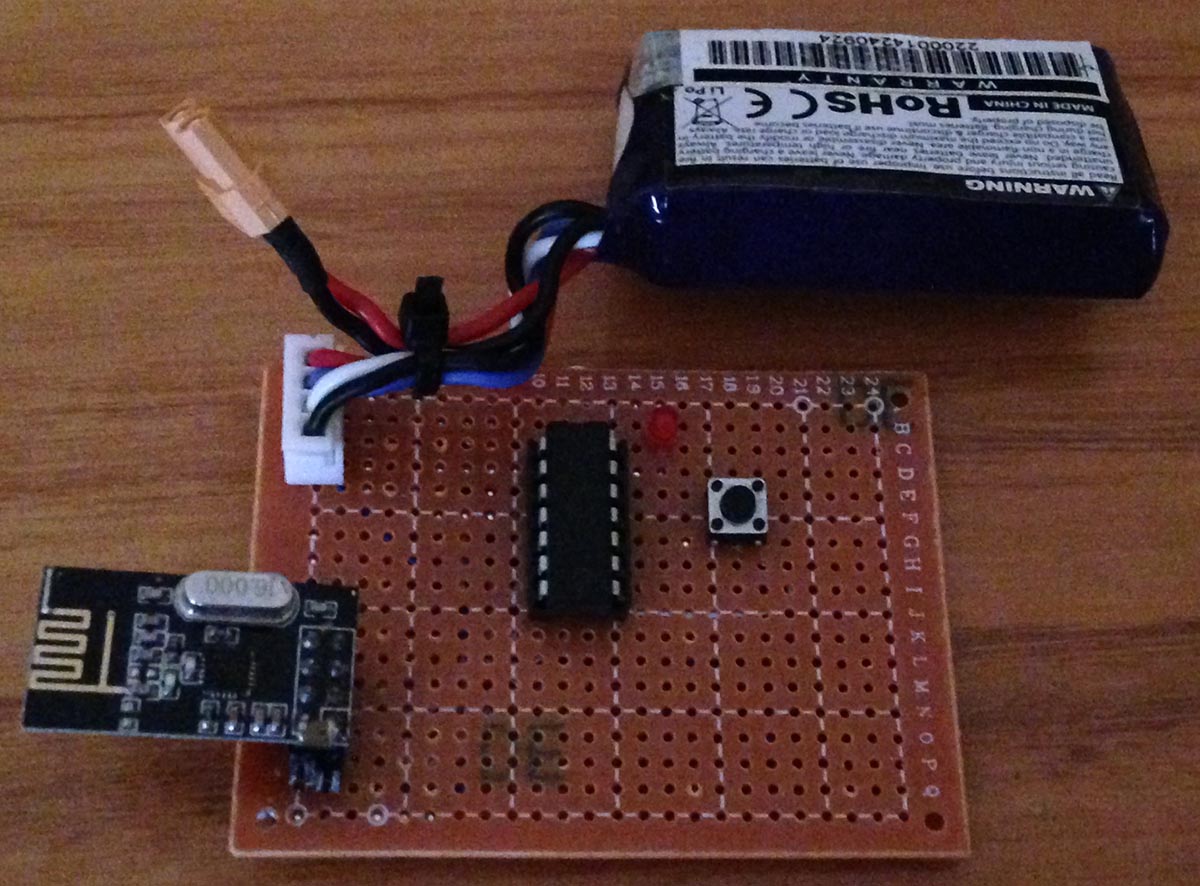
I’m thinking of using the nRF24L01 module (as it’s pretty low cost), using an ATtiny24/44/84 which should give us 6S support and have it powered from the first cell of the LiPo, it shouldn’t take too much current from the first cell as we stay in sleep/power down most of the time. Add in a few resistors, led, mosfets to turn on when we want to measure the voltage. I will coat the PCB in lacquer and cover it with heat shrink to protect against the environment and since the board needs to be as small as possible, I’m going to try the SMD version of the nRF24.
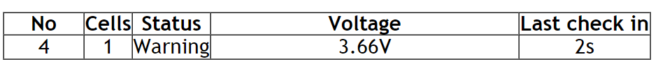
Check-in times for these sensors might be in the range of hours as battery voltage won’t change too much, it would be nice to have a graph over say 30 days but I might look into that later if I feel it’s worth doing, for the moment it will just show the sensor number, cells, status if it’s ok or not, battery cell voltages and last check in time. Server side would just be an ESP8266 with the nRF24L01 directly attached so no need for any other MCUs.
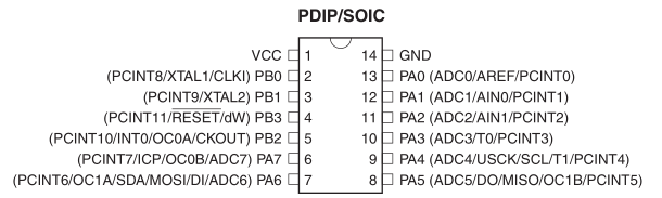
As we’ll be using the 6 ADC inputs of the ATtiny84, we can’t use hardware SPI so we’ll have to use bit-banged SPI. A little while later I tested it against an Arduino + nRF24 and it worked fine. While I was at it, I changed a little bit of the Arduino sketch and could run the same test with the ESP8266 + nRF24.
I’m going to use the CE line to also switch on all the mosfets then run the ADC on each input with 1.1V voltage reference, probably not the best to re-use the CE line but it seems to work without any issues to the nRF24.
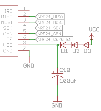
Speaking of the nRF24, we’ll need some diodes to drop the highest voltage possible of the first cell, 4.35V (LiHV, full charged assuming the worst case) down to 3.3V or so. Without the nRF24 plugged in the voltage keep rising, I added a load resistor of 1M and it stabilised around 3.3V, then I took the resistor off as the nRF24 in power down mode should consume 900nA which might be enough to bring the voltage down which it was, 3.4V, so still within spec.
With the diodes dropping voltage, I tested lower voltages on the first cell, at 3.7V no packets seemed to be transmitted anymore. I added a 10uF electrolytic and it worked until 3.5V, decided to swap it out for a 100uF and now it works down to 3V.
For protection, I added a polyfuse for the first cell going to the ATtiny. The lowest current one I could find at a low cost was a 50mA with 150mA tripping current. I tested this with a 1 ohm resistor and it works well, does get a bit hot though about 50C.
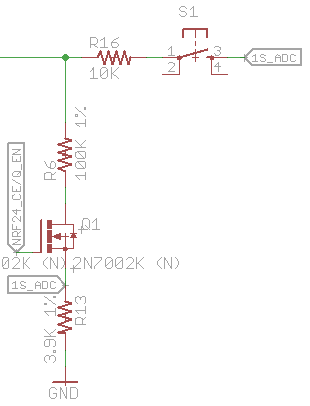
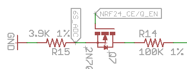
I was thinking how could I give each board it’s own sensor number easily? Programming it would be a bit of a pain. We don’t have any pins left but I added a button with resistor which would feed in the first cell voltage to the first cells ADC directly, bypassing the mosfet and resistor, it should give us a pretty high ADC reading.
void check_link_button(void) {
	sbi(ADCSRA, ADEN); // Turn on ADC
	adc_read(5); // First reading is ignored
	uint16_t buttonAdc = adc_read(5);
	cbi(ADCSRA, ADEN); // Turn off ADC

	// Button would read 812mV in the worst case
	if (buttonAdc >= 512) {
		mirf_receive_data();

		// Update var/EEPROM
		sensorNumber = data_in_out[SENSOR_NUMBER];
		linkByte = data_in_out[LINK_BYTE];
		hoursDelay = data_in_out[HOURS_DELAY];

		eeprom_write_byte((uint8_t*) sensorNumberLocation, sensorNumber);
		eeprom_write_byte((uint8_t*) linkByteLocation, linkByte);
		eeprom_write_byte((uint8_t*) hoursDelayLocation, hoursDelay);
	}
}
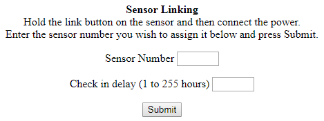
At start up if the button was held the ATtiny would go listen for packets from the server, we can send it the sensor number via the server’s web interface, store it in the ATtiny EEPROM for next boot, easy. I decided to add a “link byte” which the sensor would send the server so it only listens for it’s own sensors plus the delay time in hours (1 to 255).
// Check battery voltage
mirf_CE_hi;
sbi(ADCSRA, ADEN); // Turn on ADC
adc_read(0); // First reading is ignored

uint8_t count = 2;
for (int8_t x = 5; x >= 0; x--) {
	int batteryVoltage = adc_read(x);
	data_in_out[count++] = batteryVoltage >> 8;
	data_in_out[count++] = batteryVoltage & 0xFF;
}
cbi(ADCSRA, ADEN); // Turn off ADC
mirf_CE_lo;

// Include sensor number and link byte
data_in_out[SENSOR_NUMBER] = sensorNumber;
data_in_out[LINK_BYTE] = linkByte;

mirf_transmit_data();

uint16_t secondsCount = 0;
uint8_t hoursCount = 0;
while (hoursCount < hoursDelay) {
	watchdog_sleep(T8S);
	secondsCount += 8;
	if (secondsCount >= 3600) {
		secondsCount = 0;
		hoursCount += 1;
	}
}
Here’s how the sensor looks, CE goes high, mosfets turn on, we read all 6 ADCs and store them in the variable plus we add the sensor number and link byte. After we transmit the data, we use the watchdog sleep for 8 seconds until we hit the delay hours we have stored.
uint8_t arrayCounter = 2;
for (uint8_t x = 0; x < 6; x++) {
  double voltage = ((data_in_out[arrayCounter] << 8) | data_in_out[arrayCounter+1]) * 0.00107421875 * 26.6382;
  arrayCounter += 2;
  sensorVoltage[sensorNo][(x)] = voltage;
}

// Check for cell count
uint8_t cells = 0;
for (uint8_t v = 0; v < 6; v++) {
  if (sensorVoltage[sensorNo][v] >= 1) {
	 cells = v+1;
  }
}

// Calculate voltage on cells (can't test if highest cell is 0V)
for (uint8_t v = 0; v < cells; v++) {
 if (v >= 1) {
   for (int8_t c = v-1; c >= 0; c--) {
      sensorVoltage[sensorNo][v] -= sensorVoltage[sensorNo];
   }
 }
}
...
// Check voltage on cells (can't test if highest cell is 0V)
for (uint8_t v = 0; v < cells; v++) {
  if (sensorVoltage[x][v] <= 3.7 || sensorVoltage[x][v] >= 4.35) {
      cellsOk = 0;
  }
}
For the server side, we listen to incoming packets, grab the sensor number, check that the link byte matches (not show here), calculate how many cells it has by checking the voltage of each cell going from 1S, 2S, etc and then we calculate each cells voltage by taking away the voltage of the previous cells voltage. Later on we check the voltage on each cell.
...
noInterrupts();
timer0_isr_init();
timer0_attachInterrupt(timer0_ISR);
timer0_write(ESP.getCycleCount() + 80000000L); // 80MHz = 1 sec
interrupts();

...
// Increment uptime every second
void timer0_ISR (void) {
  timer0_write(ESP.getCycleCount() + 80000000L); // 80MHz = 1 sec
  currentUptime++;
}
Instead of using an RTC or other clock source, it’s just using a timer which works out to about 1 second every interrupt, doesn’t need to be very accurate at all, it’s just used to keep track of the last check in time, can’t recall where I found this.
Download LiPo_Battery_Storage_Monitor_v1.0
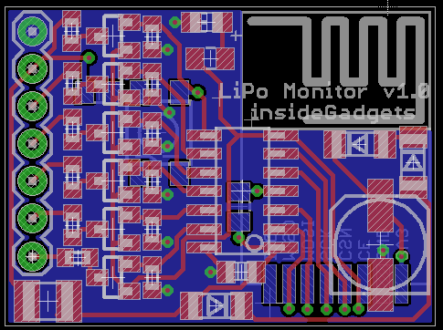
Now I’m just waiting for the nRF24 SMD modules, right angle 7 pin JST connectors and then I’ll give it another test with a 4S + 2S battery. Once that’s done, verifying the sensor PCB and server PCB will be all that’s needed, I already have the sensor PCB mostly designed as above, it might be around 2.9cm x 2cm. We could also add in email notifications when cells get too low.


I am curious which FETs you are using in your circuit.
Hi Joe,
The FET is just the standard 2N7002K N Mosfet, any N mosfet should work as long as the Vds is high enough and RdsOn is decent at 3V (even if it’s a few ohms it shouldn’t really matter). Current passing through it will be minimal – under between 50uA to 250uA.
I am looking into building a battery data logger into a an actual battery build. I need something that can track and store battery voltages for later analyses. We were using a product in one of our designs but it has since been discontinued and we would like to find an affordable alternative solution. This looks to be on the right path but I have very little experience in the components/programming side. How would I go about building something like this? If you could provide me with any insight it would be much appreciated.