Previously I built a GBA LiPo Voltage Regulator & Charger using a op-amp with an NPN transistor to regulate the voltage plus used an off the shelf LiPo charging chip, this is so we could trigger the GBA’s red light when the LiPo was at 3.7V (changed to 3.6V now). The efficiency wasn’t the best (around 62%) and I was lead down this path because I couldn’t find any DC-DC converters with low quiescent current but it turns out that I didn’t search hard enough.
The plan is to use an adjustable DC-DC converter to step down the voltage to around 2.5-3V which should result in higher than 90% efficiency and then use a MCU or similar to toggle a resistor connected to the resistor divider when the LiPo is running low.
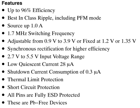
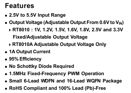
The first 2 candidates for checking the quiescent current is the OnSemi NCP1529 and the Richtek RT8010, both of which switch higher than 1.5MHz, have a 1 amp output and feature a quiescent current of less than 70uA.
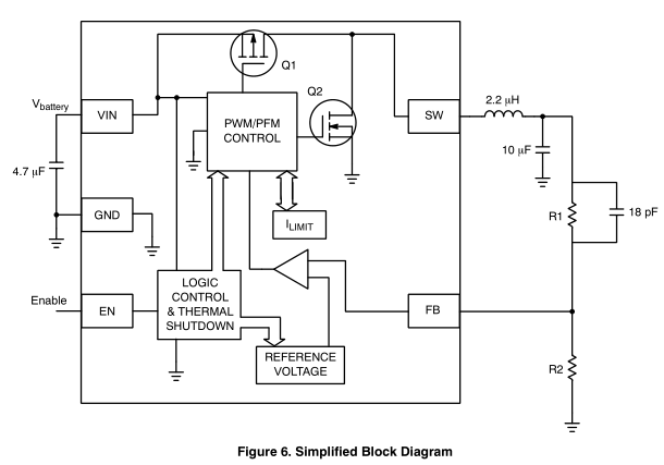
The NCP1529 looked like it might be the best option so I started with that one first. The components to add was a 2.2uH inductor with a 10uF cap, a 4.7uF cap for the input and the the R1/R2 resistor (went with 470K/120K) with a feed forward cap (I haven’t needed to use a feed forward cap before).
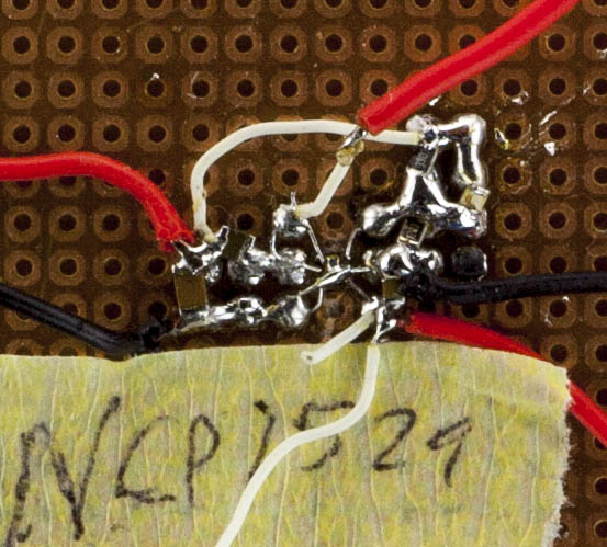
(most of the pictures don’t look too nice, this is because I’ve switch out the inductors, resistors, caps a couple of times!)
Built it all up, powered it up and unfortunately I saw about a 2mA quiescent current. I changed R2 to 220K to adjust the voltage to 1.18V and the current seemed to drop, so perhaps we need larger resistors. I changed R1 to 850K but I was back to 2mA so looks like it’s more the voltage drop that did it. I adjusted the input voltage but it only dropped to 60uA when the input voltage was above 4.8V so that won’t work, it also dropped to 100-200uA when around 3.3V.
I started playing around with it, ended up touching VREF and that’s when the current dropped, weird. So I took out the feed forward capacitor and placed it on VREF to GND and it seemed to work but when I checked it under the scope, it looked bad and under load it was still pretty bad. I added the feed forward capacitor back in and it was back up to 2mA again.
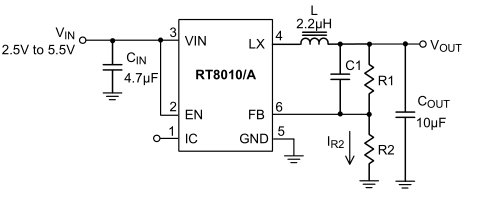
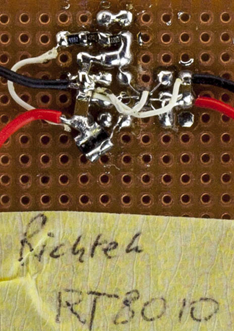
I thought I’d try the Richtek one, it’s the same sort of setup. Built it up, plugged it in and had the same issue but even worse at 10mA! I did the same VREF to GND fix and it did work, got around 40uA to 70uA but once again the noise was bad. I swapped out the inductor to 4.7uH which made the current drop to 2mA then to 6.8uH which made it rise to 10mA again.
I kept playing around with both DC-DCs but had no luck and I’m starting to think the quiescent current figures may be for the fixed voltage variants or specific use cases so I gave up for a week or two and worked on something else.
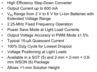
I found a comment someone made on the Dangerous Prototypes page about trying the Ti TPS6220x / TPS6226x product lines, one is 300mA output and the other is 600mA. It features a power save mode with a typical quiescent current of 15uA it all looked good on paper.
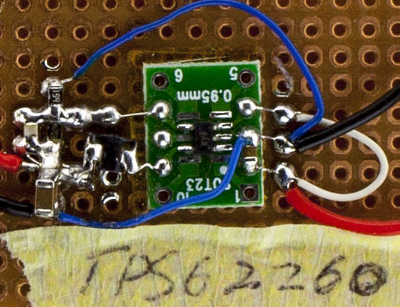
So like the others, I built it up, this time with a 2.2uH very low DC resistance (110 mOhms) inductor like the datasheet said, maybe this was a problem with the others (they weren’t too bad, 200-300 or so mOhms). I plugged it and was hoping for the best, but once again, it didn’t quite deliver but I do see it trying better than the others, it’s jumping around a fair bit between 30uA and 2mA. Sometimes it stays around the 30uA-300uA region but spikes up to 1-2mA but it depends on the input voltage, once you hit 4.2V input, there are bigger current spikes.
I added another 10uF capacitor on the output, it helped a little but there were still large current spikes at 4.2V input. I switched the inductor to 4.7uH and things changed, now at 3.4-4.1V it draws 2mA current but at higher voltages it sits around 10uA to 100uA. After changing it to 3.3uH, we’re looking better from 3.1V to about 3.9V then the current starts to increase, so we have a small gap to work.
I didn’t have any inductors in-between but I did have another 4.7uH, it was smaller than the others. I gave it a go and to my surprise it seems to be suitable, from around 3.55V to 4.8V (I didn’t test any higher), it stays around 10uA and every few seconds jumps up to 100-250uA or so, this was just with the multimeter measuring a 1 ohm shunt resistor so let’s verify it with the scope.
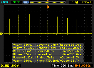
On the scope, it tells a different story, we have spikes up to 568mV, which equates to 568mA every second or so (quiescent current), seems a little high. I don’t think I’ve ever measured a DC-DC’s input current vs time before. At first I thought it might have been my power supply’s current limiting but it turns out that wasn’t it.
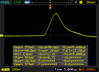
When we zoom in we can see that the spike only lasts for ~20us if that. In the zoomed out view it looked bad but once you do the calculations, it would take about 4 days to draw 1mA of current overall.
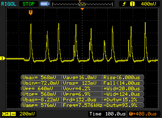
I zoomed out a little bit more and can see that every now and then there are a couple of pulses which happen all together, not all the same height but our current draw overall would go up, maybe it would be around 1-2 days for 1mA of current.
Let’s quickly test the efficiency of the 3 DC-DCs, in each section we can see the load in mA that it drew from the 4V input voltage.
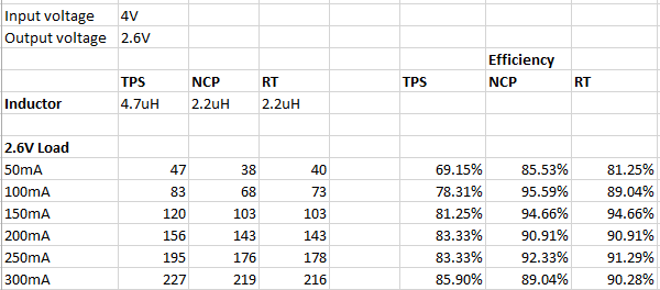
Even though the TPS has the best quiescent current, it’s performance isn’t the best compared to the others. I changed it back to the 2.2uH inductor and the efficiency only got better than the others once it went up to 250mA.
As it stands the NCP is the best option and is also the cheapest in 20+ quantities. I would probably switch to the RT if the load was going to be more than 300mA as it seems like it would become more efficient but the maximum load we might see is 200-250mA. In either case, we can’t just use any DC-DC on it’s own due to the quiescent current. My original plan was to have a low quiescent current LDO and then have it switch to the DC-DC once current draw is detected, it just means we have to find a decent sized LDO and have a bit more extra circuitry.
Another way I’ve been thinking of is putting the DC-DC in shutdown, having a 1.5V LDO with a diode connect to the DC-DC output and then connecting the DC-DC shutdown pin to the other side of the power switch. This would mean we have around 1-1.5V on the output, once the switch is flicked on, the shutdown pin would rise to 1-1.5V, the DC-DC will turn on in a few hundred milliseconds it would take over. Feeding 1.5V to the DC-DC output causes a 3.6uA to current draw when it’s shutdown, so that’s not too much to cause any problems.
I hooked it all up and gave it a go, it seems to work!
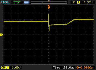
Looked at in with the scope, the DC-DC doesn’t even take 1 millisecond to take over, probably because it doesn’t have to ramp up the output voltage as it’s already sitting at ~1.8V.
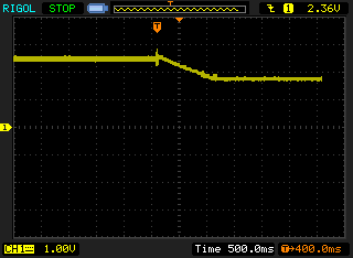
And once the power is switched off, we can see the fall time, almost 1 second.
For the next part, I’ll have to continue to test the NCP DC-DC to see if there are any issues, test switching in the resistor when the LiPo is running low and see if I can have the PCB made.


