Previously we added NES, WiiMote, N64 receivers and a Multi-RX Adapter for the Wireless Gameboy Controller. I think that pretty much covers all the receivers for now so I thought the next stage, while not related to the Gameboy directly, is to add transmitter sides to the receivers for NES, SNES, GC and N64.
Today we’ll look at the SNES transmitter board.
(sneak peak)
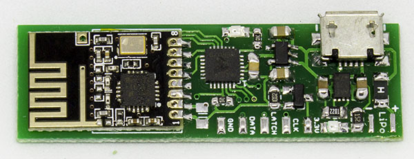
I want it to be as simple as possible to install, not like some others where you might have to wire up each button to the board, instead make it just query the SNES controller like a SNES console would. It would be neat to make an actual drop in replacement PCB – maybe something for the future. For the moment, it would mean just 5 wires to hook (Vcc, Gnd, clock, latch, data) up plus the LiPo battery, speaking of which, we’ll put a LiPo charger on the board. For the MCU, I went with the cheapest and smallest option I have used before, the ATtiny48 which can run at 8MHz. As you can see by the PCB design, I tried to make it pretty compact and not too wide which worked out quite well.
Upon testing a SNES’s controllers current consumption it’s a few mA so we can’t just leave out the SNES controller running all the time. We can choose to have a switch to turn everything on or off or just use a P mosfet instead – to keep things as nice as possible with minimal cut outs, I went with the P mosfet. But now we have to consider how to wake up, should we wire up to one button or can we do something else?
I decided on the solution of having the MCU wake up every ~8 seconds, power up the SNES controller board, wait a tiny bit, query the SNES board and see if any button is being pressed. If so, start transmitting packets and have a time out of x minutes if we find that no buttons were pressed. Speaking of which, we have to have a method to change the RF channel/address and packet per second – perhaps just holding down another button and using the up/down/left/right/L/R to change the settings.
	NRF_POWERDOWN; // Power down the nRF24L01
	while (inPowerDown == 1) {
		PORTD |= (1<<PFET_POWER); // Turn off power to SNES board
		_delay_us(50);

		// All low
		PORTD &= ~(1<<DATA);
		PORTD &= ~(1<<LATCH);
		PORTD &= ~(1<<CLOCK);

		watchdog_sleep(T8S);
When the battery is plugged in, we are in power down mode by default, so we turn off power to the SNES board and set data, latch and clock low.
		// Set latch low and clock high, data as input
		DDRD |= (1<<LATCH);
		PORTD &= ~(1<<LATCH);
		DDRD |= (1<<CLOCK);
		PORTD |= (1<<CLOCK);
		DDRD &= ~(1<<DATA);
		PORTD &= ~(1<<DATA);

		PORTD &= ~(1<<PFET_POWER); // Turn on power to SNES board
		_delay_us(200); // Wait a bit

		// Request key press state from SNES
		readController();
After the watchdog timer, we set the data, latch and clock back to their defaults, power up the SNES board and read the controller which is easy enough to do, just pulse the clock 16 times and read the data line when the clock is low.
// Select button pressed, configure nRF
if (!(controllerOutput & 0x2000)) {
	uint8_t inConfig = 1;
	nrfChannel = 1;
	nrfTx[4] = 1;
	nrfPpr = 1;

	while (inConfig == 1) {
		PORTD |= (1<<LED);
		readController();
		PORTD &= ~(1<<LED);
		_delay_ms(5);

		if (!(controllerOutput & 0x800)) { // Up, channel increase
			if (nrfChannel < 127) {
				nrfChannel++;
			}
			while (!(controllerOutput & 0x800)) { // Wait until let go
				readController();
				_delay_ms(20);
			}
		}
		...
		if (!(controllerOutput & 0x80)) { // A, finish and transmit
			while (!(controllerOutput & 0x80)) {
				readController();
				_delay_ms(20);
			}

			_delay_ms(500);
			inConfig = 0;
		}
		...
		while (1) {
			readController();
			if (!(controllerOutput & 0x80)) { // A, go back to sleep
				while (!(controllerOutput & 0x80)) {
					readController();
					_delay_ms(20);
				}
			}
I went with the select button as the configuration button, once held and the AVR is awake, we’ll keep reading the controller for up, down, left, right, L and R and the LED will turn off once a button is held and turns back on once the button is let go for some de-bouncing (the LED can be a bit hard to see if it’s in the controller). Once the A button is pressed, we store the settings and transmit the channel/address until the A button is pressed again.
To start transmitting packets, the start button needs to be held down until the AVR wakes up. We do have a problem though, how will receivers know which TX cart or board is sending the data?
Previously I’m just checking for 1 or 2 byte nRF packet length however when switching to packet lengths higher than 3, it can still potentially match up with a TX transmitting 1 or 2 bytes – I saw this happen a few times. I thought if the RX packet length didn’t match the TX then it wouldn’t accept the packet but it turns out that if the TX packet length is less than or equal to the RX packet length, then the RX will accept it. For controllers such as the GC, it may have a 8 byte packet length.
We could have the first byte become the “controller type” however the GB and GB TX carts don’t have this functionality and I don’t want to have to ask users to update their carts firmware especially for the GBA TX cart – would be quite painful. After a bit of playing around I found a solution which seems to work.
We will have the nRF packet length when checking for a receiver be 9 bytes. As the GB and GBA TX carts can’t possibly press up and down or left and right at the same time, we can use that to our advantage. For up and down, the bits that are transmitted are 0x20 and 0x10, so we could make the receiver check for 0x30 and use the lower 4 bits to assign which controller type it is, e.g. SNES 0x31, GC 0x32, etc.
As the packet length is 9 bytes, it will accept either the GB/GBA TX packet but we don’t know which we end up accepting. We could ask the user not to press anything when powering up and then see if the second bytes reads 0x00 but there are some receivers which use button presses at start up to change button mappings.
Actually, that brings something else up – what happens to the data read out if a GB/GBA packet is received? What does the 2nd byte look like if it’s a 1 byte packet and we are always reading out 9 bytes. I didn’t want to get the logic analyser out so I kept comparing it to a different value until I hit the right value – 0xBF.
// Read out
for (uint8_t x = 0; x < payloadSize; x++) {
	multiTxData[x] = spi_transfer(0);
}
mirf_CSN_hi; // Pull up chip select
mirf_config_register(STATUS,(1<<RX_DR)); // Reset status register
mirf_flush_rx_tx();

// Check mode
if (multiTxData[0] == SNES_TX) {
	modeFound = SNES_TX;
	payloadSize = 3;
	mirf_config_register(RX_PW_P0, payloadSize);
}
else if (multiTxData[1] != 0xBF) { // GBA mode
	modeFound = GBA_MODE;
	payloadSize = 2;
	mirf_config_register(RX_PW_P0, payloadSize);
}
else if (multiTxData[1] == 0xBF) { // GB mode (0xBF means no data in that byte)
	modeFound = GB_MODE;
	payloadSize = 1;
	mirf_config_register(RX_PW_P0, payloadSize);
}
So this means, when we listen for 9 bytes, receive a packet, read out 9 bytes, if the first byte matches the SNES TX then we set the mode/payload to that. If the packet length received is 1 (GB TX cart) then the 2nd byte will be 0xBF. The GBA TX cart only uses the low 2 bits for L&R so we can safely assume that if the 2nd byte isn’t 0xBF (because the 2nd byte will only ever be 0x03 or lower) then it’s the GBA TX cart transmitting. Quite a strange/complex way to detect it but sometimes you have to just roll with it when you can’t change it!
else if (multiTxData[1] <= 0x03) { // GBA mode
	modeFound = GBA_MODE;
	payloadSize = 2;
	mirf_config_register(RX_PW_P0, payloadSize);
}
else { // GB mode
	modeFound = GB_MODE;
	payloadSize = 1;
	mirf_config_register(RX_PW_P0, payloadSize);
}
Edit: Turns out the 0xBF method didn’t quite work properly if a key was held down which I thought it might have. Instead I’m not checking for the 2nd byte being less than 0x03 for GBA mode and anything else we assume GB mode.
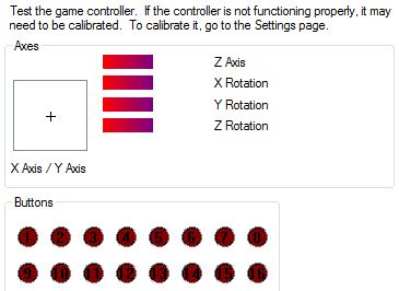
As we plan to have Gamecube controller support which has 2 joysticks, a D-pad, L&R squeezing buttons plus a few regular buttons, we have to expand the USB receivers joystick/gamepad options. I was able to add in some sliders for the other joystick which I might assign to be Y & Z rotation and I guess I’ll make the Z axis / X rotation be the L&R buttons.
Another way instead of using the y, z rotation for the camera joystick would be to list another joystick in the HID descriptor or to use the “point of view hat” option that I’ve seen some other USB adapters but I’d need to find an example on it. Edit: Point of view hat just turned out to be similar to just button pressing.
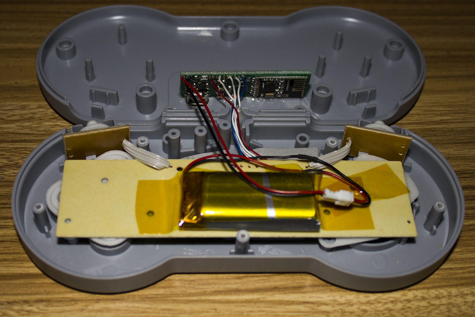
Once everything tested fine, it was time to put it all together and give it a test. I was able to mount it on it’s side and glue it in place so the USB port for the charger sticks out the back after I cut it out. I’m using a 700mAh LiPo battery which fit nicely into the case without much pressure being applied to it, it should last for about 40-50 hours of game play time.
I opened up a genuine SNES controller which has a larger PCB so this mounting style won’t work on that so I’ve decided to make another TX board with the USB connector rotated 90 degrees so that it can fit flush on the controller PCB. Once that’s received and tested and I’ve updated all the receivers to support this board then I’ll be ready to list them on the shop.


