With all of the recent GBC/GBA LCD upgrades available, it made me interested to learn more about LCDs and the signals to make them work, a subject which I hadn’t explored before thinking it might be a bit complex. Let’s take a look at the 40 pin GBA LCD and how we can change certain signals using a CPLD.
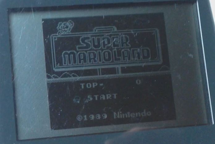
(Sneak peak)
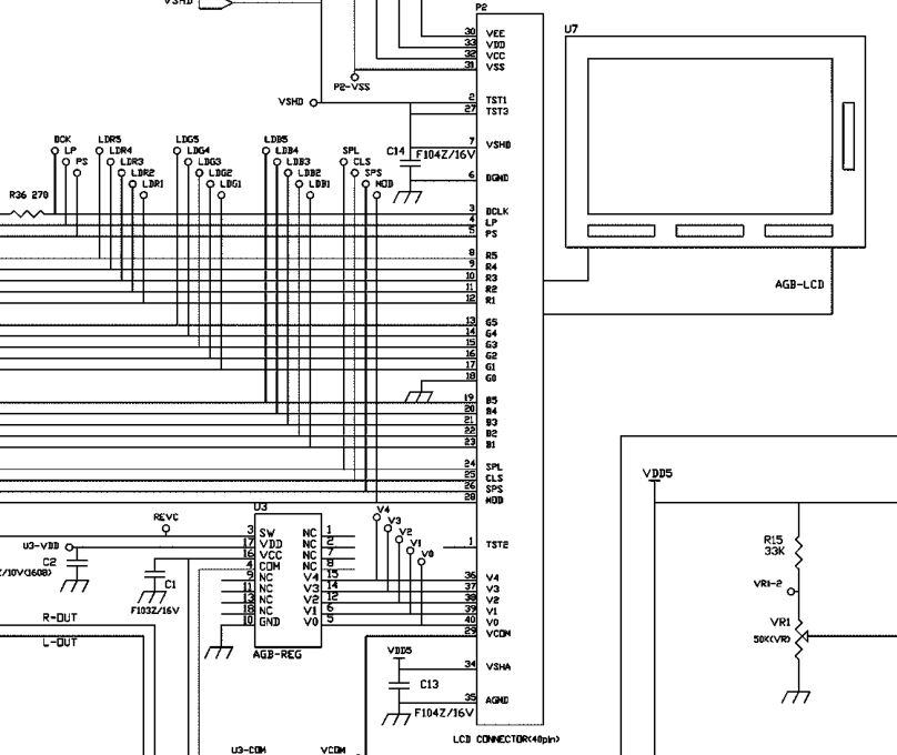
Firstly, we’ll take a look at the GBA schematic which shows the LCD screen and all the connections going to it. It looks to have a fair few voltages required by the 40 pin LCD supplied by the AGB-REG chip while the 32 pin LCD on more recent GBA don’t require these voltages and thus don’t require the regulator chip.
We have signals DCLK, LP, PS, R1-R5, G0-G5, B1-B5, SPL, CLS, SPS and MOD but what do they do? For that we’re going to have to get the logic analyser out! Before we do, just by the naming, we can tell that we’ve got Red (R1-R5), Green (G0-G5) and Blue (B1-B5) so it’s 16 bits but since G0 is grounded we have 15 bits of colour.
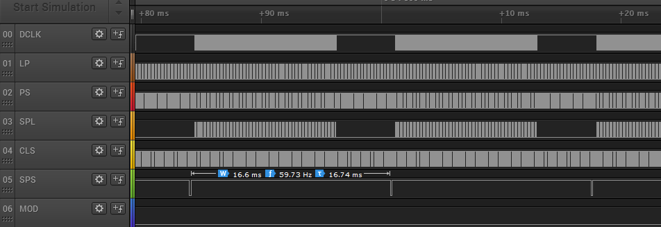
Here’s how it all looks zoomed out a bit. We can see that the SPS signal has a duty cycle of 59.73Hz which is the screen refresh rate on the GBA.
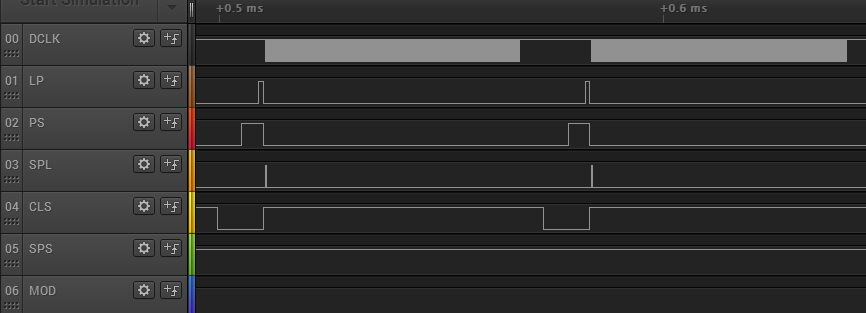
Let’s zoom in a little more, we can see that most of the other signals LP, PS, SPL, CLS seem to occur around the same time and at the start of DCLK.
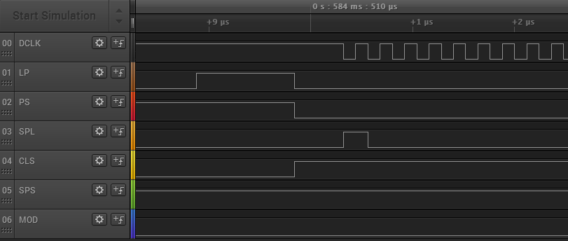
Now we can see DCLK, it appears that it’s active on the negative edge so the RGB bits ( not shown) change on the negative edge. If we count the number of DCLK pulses we get 240 – that’s the same as the LCD screen size (240 x 160). So for each pulse of DCLK, the LCD would update the RGB values and move 1 pixel to the right.
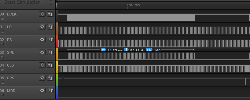
LP, PS and CLS are always running while SPL only seems to run when DCLK runs, lets count how many negative edges that one has – 160. For each pulse of SPL, the LCD moves vertically down by 1 pixel. SPS might be the signal to tell the LCD to refresh.
That was easy! We’ve now the basics to understand what the GBA is sending the LCD and could potentially change the RGB values, DCLK or SPL to our liking. But what do the other signals do – I’m not too sure but we don’t need to worry about them unless you want to drive the LCD yourself.
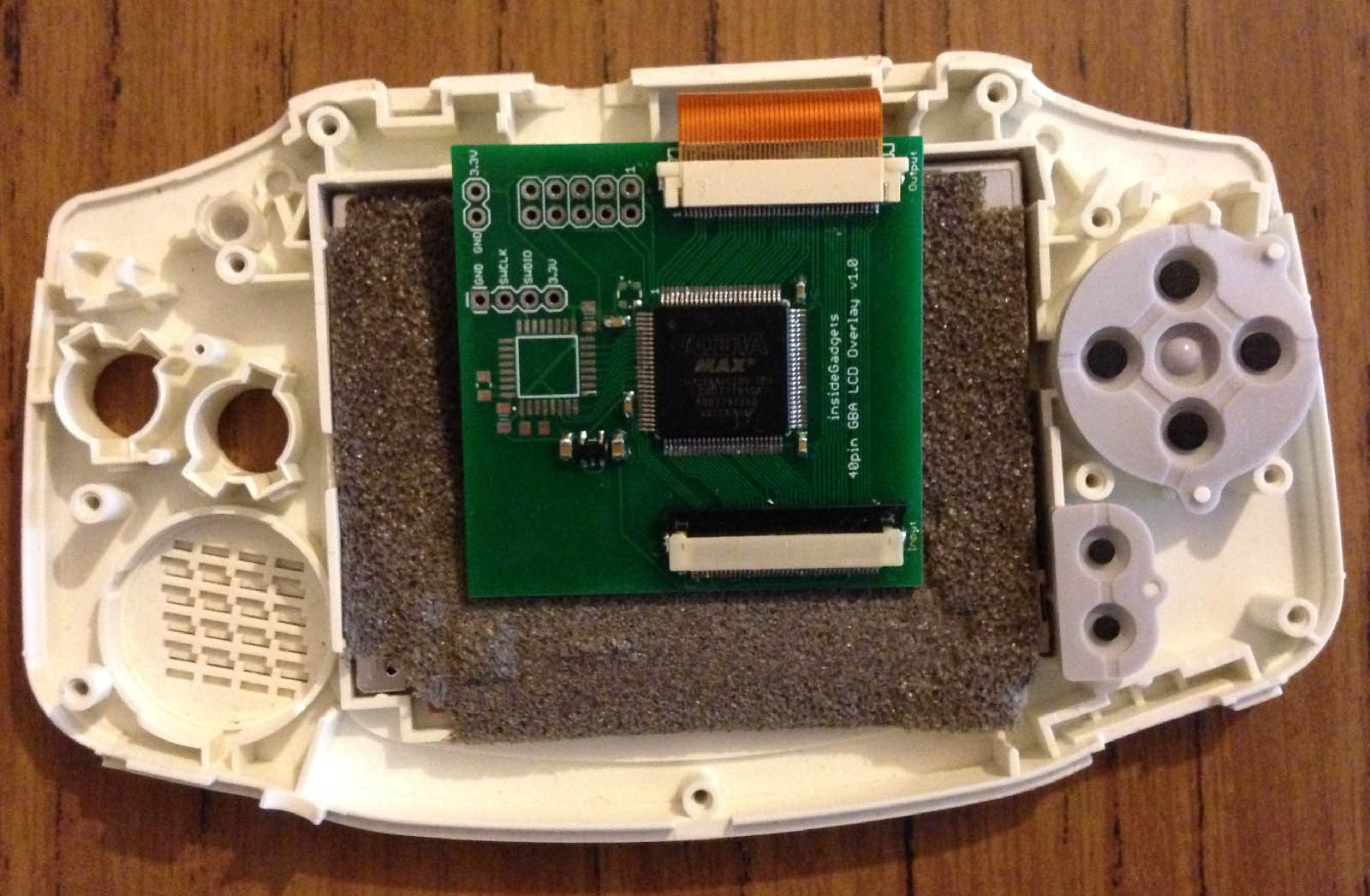
Let’s pop in our CPLD board with our 40 pin FFC connectors and have all the digital signals plus the RGB pixels (not any LCD voltages) come into the CPLD and have all these as outputs on the CPLD.
always @ (dclk, lp, ps, spl, cls, sps, mod) begin
	out_dclk <= dclk;
	out_lp <= lp;
	out_ps <= ps;
	out_spl <= spl;
	out_cls <= cls;
	out_sps <= sps;
	out_mod <= mod;

	out_red <= red;
	out_green <= green;
	out_blue <= blue;
end
The first test is to just assign all inputs to the outputs to make sure the CPLD isn’t doing anything to them and that we have our wiring right. Turns out I messed up the green pixel output channel assigning them to input only pins on the CPLD so a few mod wires later and we’re looking good.
Do you want to do a Bivert? We can simply do a not of our RGB (out_red <= ~red). You could play around with colours, maybe only show red and green, add 2 colours together or add a few bits to each. How about changing colours every x amount of frames? You could do that by setting a negedge on SPS and increment a counter.
if (SPSCounter[3:3]) begin
	out_red <= red;
	out_green <= green;
	out_blue <= blue;
	out_sps <= sps;
end
else begin
	out_sps <= 1;
end

always @ (negedge sps) begin
	SPSCounter[7:0] <= SPSCounter[7:0] + 8'b1;
end
Would you like to drop frames? We can set a counter on the SPS signal and only update the output every x times.
How about a sort of glass shimmering effect? A good amount of these effects are just found by chance.
if (dclk_counter[2:2]) begin
	out_red <= red;
	out_green <= green;
	out_blue <= blue;
end

always @ (negedge dclk) begin
	if (spl) begin // Clear DCLK
		dclk_counter[7:0] <= 8'b0;
	end
	else begin
		dclk_counter[7:0] <= dclk_counter[7:0] + 8'b1;
	end
end
By counting the DCLK pulses and only updating the RGB values when the 2nd bit is set on the DCLK counter.
What about some weird sort of scan lines?
if (splCounter[0:0]) begin
	out_red <= red;
	out_green <= green;
	out_blue <= blue;
end
else begin
	out_red <= red + 4'd4;
	out_green <= green + 4'd4;
	out_blue <= blue + 4'd4;
end
We can increase the RGB values by 4 on every 2nd vertical line.
Probably the best use might be for generating borders on GB games, so instead of the usual black borders you could have them match the game’s colour.
if (dclk_counter >= 8'd40 && dclk_counter <= 8'd199 && spl_counter >= 8'd10 && spl_counter <= 8'd150) begin
	out_red <= red;
	out_green <= green;
	out_blue <= blue;
end
else begin
	out_red <= 5'h16;
	out_green <= 5'h16;
	out_blue <= 5'h1F;
end
All we need to do is have a counter on DCLK and SPL, then find where the actual GB frame starts and ends both vertically (SPL) and horizontally (DCLK) which I found to be 10 to 150 and 40 to 199.
Potentially an improvement could be to have the CPLD detect the colours on each side and then on the next frame, you would update the borders to match. Another option could be to have the user select the RGB colour with the L, R and A buttons hooked up to an MCU which stores the config in the EEPROM and updates the CPLD at boot or when the colours are updated. You would also need to detect whether the game was GB or GBA as you don’t want the borders on a GBA game!
I was planning on using an STM32 48MHz which could potentially override the pixels, perhaps store some text in flash, load it to SRAM after each horizontal line however it didn’t appear to be fast enough for that.


I’m trying to drive this LCD screen,could you give me some information or advice?