From the last part, we looked at the client/server interaction, server communication with the ESP8266, used an EEPROM to keep an event log/sensor names and added a RTC. Today we’ll add a simpple admin page to set things like the RTC, sensor names/types, email addresses for which we’ll also have the ESP8266 send us email alerts plus have a look at a PIR interference issue, various other small improvements/fixes and a quick look at PCBs and 3D printed case; a lot to cover!
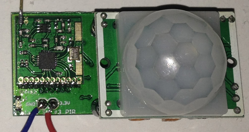
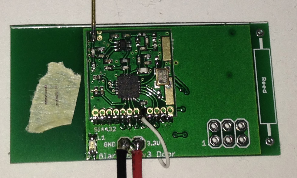
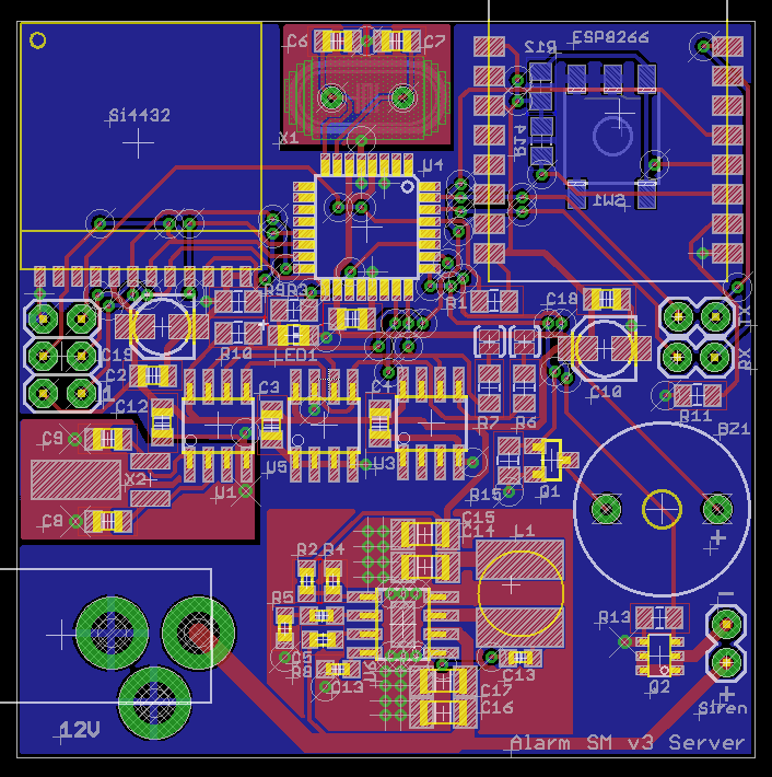
The PCBs arrived a few days after I posted the last part so I built them up and tested them, it all seemed to work apart from the door sensor, 2 traces were touching each other (my mistake) so I just cut the track and re-wired it.
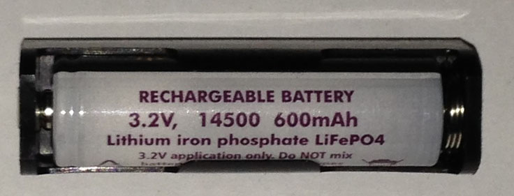
The Zippy 700mAh LiFe battery I was originally planning to go with went out of stock so I went looking for other LiFe options, turns out there is a 600mAh 14500 size which just fits a AA battery holder. If I had of re-done the PCB I could have made it a bit bigger to fit the AA holder on the back. Pricing wise, it costs a bit more ($10 for 2) but for the form factor that it offers I think I’ll stick with it.
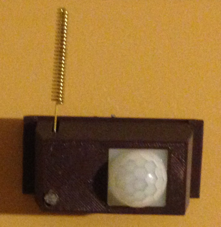
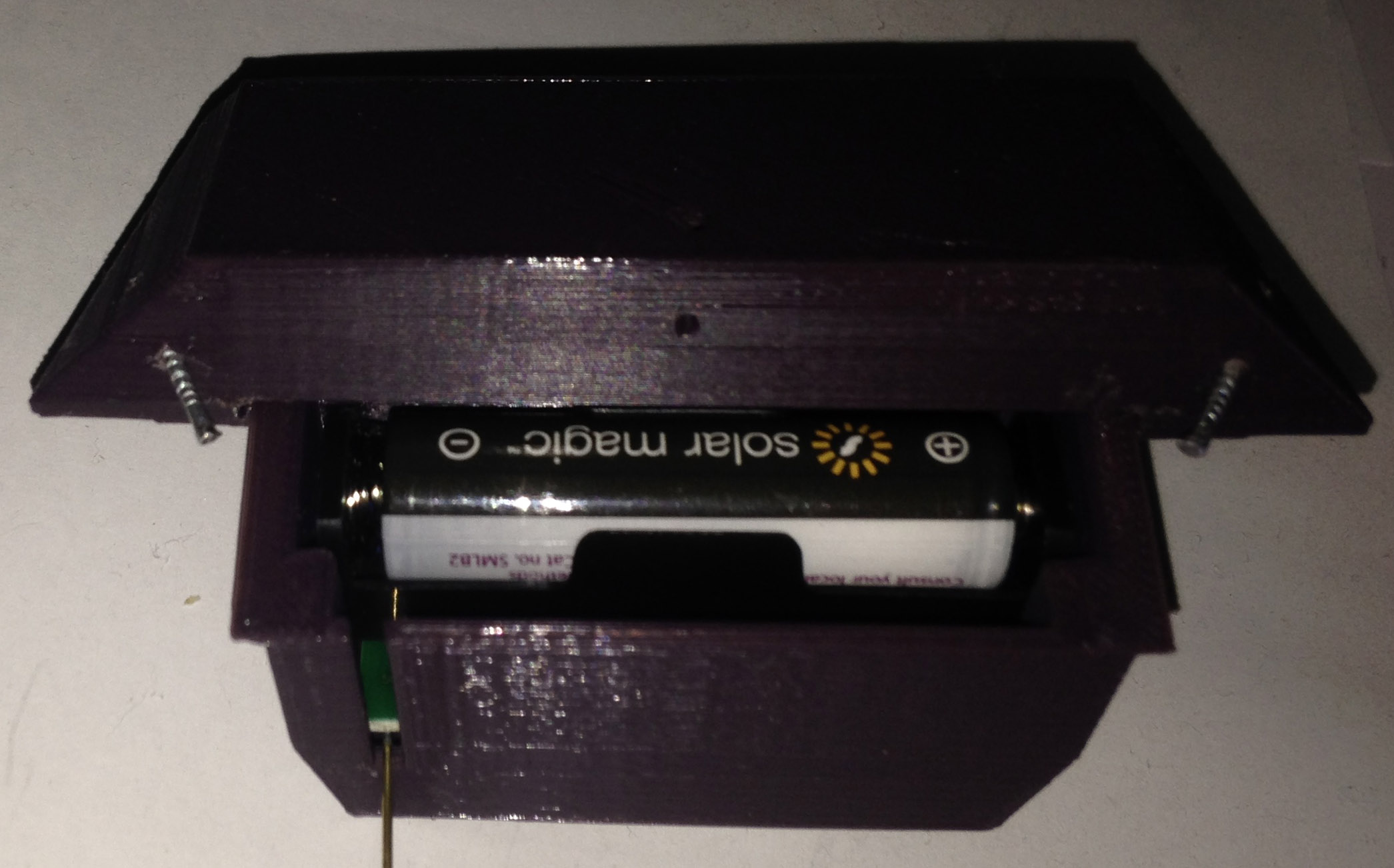
For the 3D printed case, I made something as small as possible that would fit the PCB, PIR sensor and a slot for the antenna that pokes out. I ended up putting the LiFe battery on the back of the PCB anyway with a cutout that fits it. If you look at it front on, it doesn’t look too bad, but from the side, it does look a bit bulky but it’ll do. The LED is on the bottom left of the PCB, kind of hard to see with the case on; you could use transparent material but I didn’t have any, so I made a little hole and inserted a plastic light pipe which does the trick. Later on I think I’ll paint the cases.

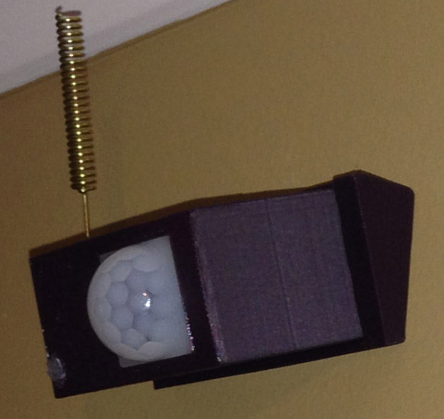
The next part was the wall mount and how the case would attach to it, so that the wall mount could be positioned, nailed to the wall and then the sensor attaches to it easily. I thought about making it clip into place but that design might be a bit too complex so I went with a sliding mechanism instead, the case just slides down into the wall mount. The wall mounts have 25 degrees tilt with 3 small holes to nail it to the wall, one in the middle if it’s mounted straight on the wall and the 2 other holes would be used if positioned on the corner of the wall, it works well.
PIR Interference
I left the PIR sensor running when the alarm system was on, I found that it seemed to trigger by itself every few seconds, this used to be a symptom of low voltage to the PIR and I tried all sorts of things to correct it but then found that moving the PIR sensor away from the PCB worked. I started testing for RF interference which as you can see, it does product a bit of a spike, enough for the PIR sensor to trigger. There are certain spots on the PIR that are less sensitive. I tried reducing the Si4432 output power to 1dBm but it would still happen.
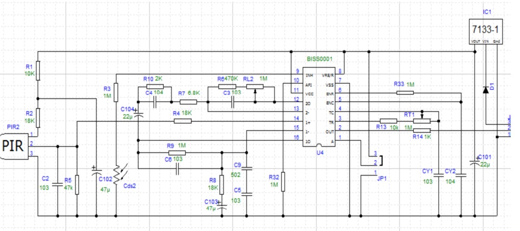
I started to draw up the circuit diagram but then I found it online (HC-SR501), I was playing around with adding a bit of a load to the “2 out” pin of 100K to 1M but it didn’t really help too much or it reduced the sensitivity too much. I decided to try adding a 0.1uF capacitor to the “2 out” and “2-” pins, sort of to reduce the frequency response of the op-amp; and to my surprise it worked. Sensitivity is reduced a bit, the spike still shows a tiny bit but it doesn’t cause it to trigger. I tried a 0.2uF capacitor but that was a bit too much and sensitivity is greatly reduced.
Other mods to do to the PIR sensor is to short out the input diode and 3.3V regulator as the battery will be supplying 3.3V directly.
Admin page
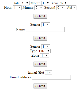
The admin page is just a very basic page which lets us enter in the RTC via drop down boxes, sensor names for the sensor numbers, the type and zone of each sensor and email addresses for the 3 email slots available.
if (server.hasArg("sensorname")) {
    temp += "Sensor = " + server.arg("sensor") + "<br/>";
    temp += "Name = " + server.arg("sensorname") + "<br/><br/>";

    Serial.print("N-");
    Serial.print(server.arg("sensor"));
    Serial.print("-");
    Serial.print(server.arg("sensorname"));
    Serial.print("-");
}
We can easily check if a particular form was submitted by checking if the argument exists and then read the values and send it off to the ATmega which will process it.
Sensor types/zone
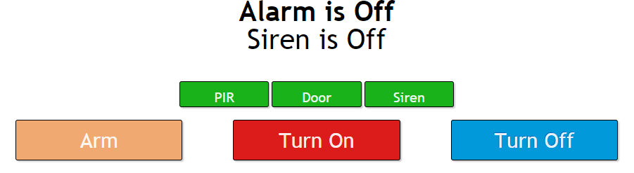
I’ve added sensor types and zones so that we can select which sensors to activate when the alarm is switched on, be it just PIR sensors or door sensors; if it’s green then they are active, press on them and it changes to red. This can also apply to sirens too, if you wanted to have the main siren be active or you could add tiny buzzer instead (say if you were in the house and only wanted door sensors active).
if (sensorTypeArmed != 0xFF) {
	// Read EEPROM to see sensor type
	soft_i2c_eeprom_read_x_bytes(EEPROM_ADDR, ((RH_RF22_fromAddress-1) * 64) + sensorTypeLocation, 1);

	// If bits match, set to on if we are armed (eepromBuffer[0] contains the type - 1, 2, 3)
	if (sensorTypeArmed & (1<<(eepromBuffer[0]-1))) {
		systemStateToSend = systemState; // Set state
		if (systemState == SYSTEM_ARMED) { // Set sensor to on if we are armed
			systemStateToSend = SYSTEM_ON;
		}
	}
	...
The ESP8266 sends an 8 bit value, each type is 1 bit, if all bits are on then it reads 0xFF, if not then we check the sensor type as the sensor number checks in; bit 0 would be PIR, bit 1 would be Door, etc.
At the moment I’m still testing the PIR modules to see if zones are really required, i.e 2 PIR sensors per zone, both would have to go off around the same time for the alarm to trigger. From the current alarm system I thought they might be because it sometimes triggered by itself but I’m starting to think it was a faulty door sensor.
Email alerts
For the email alerts I just needed something simple, I stumbled upon the esp8266-sendemail repo on Github which is very easy to use, I did need to make a little modification to get the from names working so it would say from “Alarm System” instead of the email address – Download esp8266-sendmail-mod
for (uint8_t x = 0; x < 3; x++) {
	if (strlen(emailAddresses[x]) >= 5) {
		SendEmail e("mail.yourisp.com", 25, "", "", 2500, false);
		e.send(emailFromName, emailFromAddress, emailAddresses[x], "Alarm on", "Alarm on");
	}
 }
We just loop through the 3 email addresses on file and send the email out, the ESP8266 doesn’t respond to any requests until it’s done, the default time out is 5s which is a bit long, I was able to reduce it to 2.5s.
ATtiny / ESP8266 bug fixes
I was having some weird lock ups on the sensors, it seemed like the ATtiny wasn’t doing anything after a while and pulling the reset line low didn’t help either, only a power cycle resolved the issue. Eventually I started taking things out of the code until I removed all the Si4432 interrupts which seemed to resolve the issue.
void watchdog_sleep(uint8_t timeout) {
	setup_watchdog(timeout);

	// One last check to see if sensor isn't triggered before sleeping
	if (sensorTriggered == false) {
		system_sleep();
	}
	turn_off_watchdog();
}
I don’t have a copy of the code but I believe it was like the above, I believe what may have been happening is that some how the watchdog wasn’t being disabled properly, it was resetting the AVR and because I have a 500ms delay at start up, it just keep resetting. How it ties into the Si4432 interrupts is that the check sensor triggered was also occurring when sending or receiving packets which I didn’t think about properly.
void setup(void) {
	// Turn off watchdog
	MCUSR &= ~(1<<WDRF);
	CCP = 0xD8;
	WDTCSR = 0;
After removing the sensor triggered line from the code it all worked normally, I moved that piece of code to occur only once, before we touch anything to do with the watchdog and sleep for 8 seconds. Also for good measure, I disable the watchdog at start up should any problems happen with it in the future.
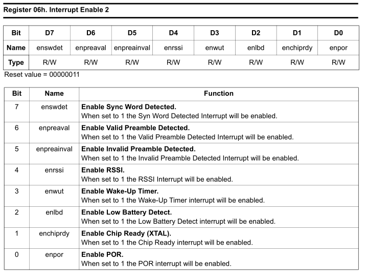
I was also having the interrupt pin go low when we were about to send a packet so had to clear the interrupts twice. I tracked it down to having the Si4432 interrupt 2 on by default, the enable chip ready (XTAL) would turn on before the packet got sent. Setting interrupt enable 2 to all 0’s resolved this issue.
WiFi.mode(WIFI_STA);
WiFi.begin ( ssid, password );
For the ESP8266, I found that my phone would lose internet connection sometimes, I think this is because I had once connected it to the 8266 and the Wifi AP mode was actually still enabled on it by default, oops, didn’t know it could do both AP and station mode. We just set Wifi.mode to be a Wifi station only.
After I made that change weird reboots started occurring on it, usually after 2-5 hours. I reverted to older code but the same issue happened. After trying various things like power supply, cabling, etc, I disconnected the UART from the ATmega and the issue didn’t occur, now I started testing for issues with buffers / lack of memory by sending data to the 8266 UART quickly, the issue occurred again. I removed all UART handling except to the buffer and it still happened.
Eventually after searching a lot for random crashes / reboots, I came across the Github issue “AttachInterrupt random crashes”. I disconnected the RTC MFP cable (which sent 2 pulses per second) to the 8266 and everything worked again, how odd as I had been running it with that cable for a while.
void ICACHE_RAM_ATTR uptimeUpdate(void) {
    rtcUptime++;
}
The way to resolve the issue is to make the function the interrupt calls to be loading in RAM by adding the ICACHE_RAM_ATTR to it as above. I could get the reboot to happen within 20 minutes when sending UART requests once every 200ms and now it’s all working fine again, weird one.
Various Improvements
Xor’ing sensor number/system state
Previously when the sensor and server were communicating with each other I would take the system state and replace the first byte of the random number with it. This would end up lowering the effective bits from 256 bits to 248 bits of the random number and also the HMAC verification (as I replaced the first byte with the system state).
// To verify sensor number/system state hasn't changed, XOR our sensor number with the first byte of the random number
// and XOR the system state received with the second byte
randomNumber[0] ^= RH_SENSOR_NO;
randomNumber[1] ^= RH_RF22_systemState;
I thought why don’t I just XOR it instead, only a few bits would be flipped anyway so that’s what I did. I also have added the sensor number to be XOR’d with another byte too so that the sensor number can be verified and that it also can’t be changed. Say sensor 2 sent a request, it would have been possible to change it to come from sensor 30 which might not exist. If you took the time to intercept radio traffic, the easiest way to defeat the system would just be to jam the radio traffic all together.
Watchdog inaccuracy compensation
// Send a few times to compensate for client's watchdog timer inaccuracy
for (uint8_t x = 0; x < 5; x++) {
	send_packet(CHECK_IN_REPLY, &dataBuffer[1], 32);
	_delay_ms(5);
}
I found that some sensors would be a little bit more sensitive with the watchdog timer, they would run a bit faster or slower and not receive the server reply properly which is expected, so I’m now sending the packet from the server a few times like I used to do in the old alarm system.
Si4432 slightly lower current consumption
uint8_t RH_RF22_wait_for_transmit(void) {
	PCMSK0 |= (1<<nIRQ_INT); // Enable interrupt
	watchdog_sleep(T16MS);
	PCMSK0 &= ~(1<<nIRQ_INT); // Disable interrupt
	RH_RF22_setModeStandby(); // Set to standby as quick as possible
With the Si4432 on the sensors side we were always in idle mode (RH_RF22_XTON) which would give READY mode that is 800uA consumption when we were about to send a packet or after we received a packet to read it out. You probably wouldn’t notice it as it would only be there for a few milliseconds. I tested going to standby mode straight away after receiving a packet and not going to idle sleep at all anymore before sending a packet, it all continued to work as normal so that should a little bit more current saving.
Auto adjusting dBm power output
if (checkInCounter <= 10) {
	if (si443OutputPower < RH_RF22_TXPOW_8DBM) {
		si443OutputPower++;
		RH_RF22_setTxPower(si443OutputPower);
	}
	checkInCounter = 0; // Reset
}
else if (checkInCounter >= 120) { // It takes a lot of successful requests to reduce our transmit power
	if (si443OutputPower > RH_RF22_TXPOW_1DBM) {
		si443OutputPower--;
		RH_RF22_setTxPower(si443OutputPower);
	}
	checkInCounter = 0; // Reset
}
I had all my sensors checking in at 8 dBm but this sort of power isn’t need if you are close or only a room or two away. What I did was have a variable keep track of the check ins, if there were successful check-ins it would go positive and unsuccessful ones would negative. If we reach -10, reset the counter and increase our dBm power to the next level up until we reach 8 dBm. If we reach more than 120 positive, lower our dBm power. This should save quite a bit of power if the sensors can stay at 1-2 dBm. When transmitting the alarm triggered to the server, I boost that check in to 8 dBm as it’s the most important packet to send.
Validate alarm triggered was received
if (RH_RF22_rxInfo == ALARM_TRIGGERED) {
	atsha204a_command_nonce(dataIn, DELAY_STD);
	atsha204a_command_hmac(DELAY_STD);
	_delay_ms(10);

	// Send a few times to compensate for client's watchdog timer inaccuracy
	for (uint8_t x = 0; x < 5; x++) {
		send_packet(CHECK_IN_REPLY, &dataBuffer[1], 32);
		_delay_ms(10);
	}
}
Talking of triggered check-in’s, it would be a good idea for the server to respond to the client’s triggered HMAC response so we know that the server received the HMAC. The easiest way is to generate a HMAC using the HMAC response we received as it would act like a random number so that’s what I did. There is a limit to how many times the client tries sending the alarm triggered request before it gives up, 10 times at the moment with 500ms sleep in-between.
I think that should cover most of the improvements so far and I think it’s very close to being finished. Download AlarmSM_v3_Test2
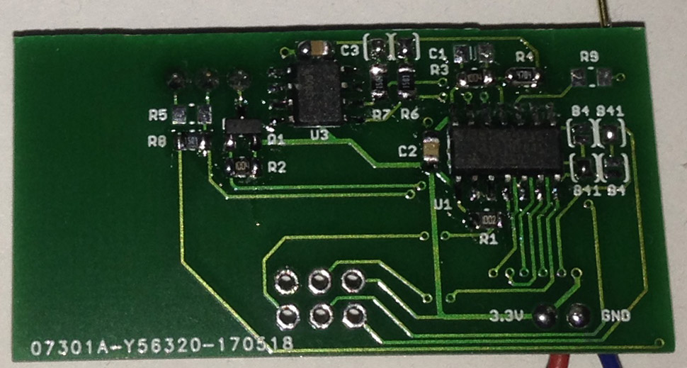
The server PCB has been designed with a 12V input supply going to a DC-DC set to 3.3V to power everything. We also have a little buzzer as well as a N mosfet to drive 12V siren too. I was thinking of battery backup, how that would be configured, etc but I thought I’d just design the server PCB without it to get it out quicker and leave my options open (12V battery or 4x LiFe batteries or 1x LiFe battery if no 12V siren, etC) or just have it covered by the UPS and test the uptime.
Now I just need to build up more PCBs, do a case for the door sensor which will be similar to the PIR one, setup the siren board (likely I’ll just re-use one of the PCBs and put an N mosfet on it), receive the server PCB and keep testing the system out, so the next part should hopefully be the wrap up which might take 1-2 months until I know it all works well.


