Previously I was looking at making a Dual Output Linear Power Supply, the prototype was working but while designing the PCB it would end up being large, a bit heavy with the heat sinks and I don’t think I would really need a linear power supply, it was a nice idea.
So it’s back to the drawing board as to what I really need, I do still have the SPPS which works but maybe it’s time for an upgrade and now that I know a bit more about DC-DC converters we can stick in the Richtek DC-DC chip instead of using an Ebay DC-DC module. We might as well switch out the 8 digit LED display for an 0.96″ 128X64 OLED SSD1306 display which I’ve seen a lot of projects move to.
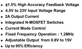
The DC-DC converter I’m looking at using is the RT8292B which runs at 1.2MHz versus the 400KHz of the RT8293A which I was using previously, it looks to be almost identical except that it will allow us to use a smaller inductor.
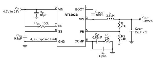
Like we’ve done before, we will use a 10K resistor for R1 and 10K digital potentiometer for R2 to control the output of the DC-DC.
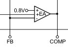
The DC-DC would be trying to keep the feedback pin to 0.8V. In the worst case if our 10K pot was shorted to ground, at 15V output only 1.5mA would flow through the R1 10K resistor, the most that most digital pots can handle is only a 2-3mA through the resistor network and it shouldn’t exceed 0.8V as mentioned before so we are good in that respect.
One problem does arise like it did before in the SPPS is that on the higher voltages say 8V and above, each step results in say 0.3-0.7V of change which is quite a bit and this is using a 10K 256 step pot in which each step is about 39 ohms. The next step up is a 1024 step pot but at $8 a pop that’s too much, what we really need is to be able to add around 0 to 39 ohms in circuit. Adding another 1 or 2K digital pot with 128+ steps would be nice but they are in the $5 range and you need to have at least one of those pots don’t tie the resistor network to ground.
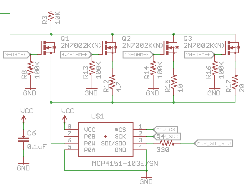
So my solution – why not make a basic version of a digital pot, 3 resistors with 4 N mosfet connected before the digital pot so the MCU can switch these mosfets on or off. The 3 mosfets would have resistors, 4.7 ohm, 10 ohm and 20 ohm and one is a pass through, you would also need to account for the N mosfet’s Rds which might be 1-5 ohms or so if not fully switched on.
Granted that now we have increased the loop area which will increase the risk of more feedback noise, that’s something that I will need to do more testing on however for the time being, I’ve tested it and it does give me more voltage range to work with, we can get close to 0.1-0.2V per increment now at higher voltages.
For the current limit, I can re-use the current limit design from the linear power supply, just a DAC connected to an N mosfet with an op-amp comparing the current running through a 0.1 ohm resistor versus what the DAC sets.
0.96″ 128X64 OLED SSD1306 Display
I went with a white OLED display and the SPI version but I probably should have gone with the I2C one instead to save some pins. The first step as always is to check that it works and I used the Adafruit SSD1306 library with an Arduino, at first it didn’t seem to work but then re-soldering the header pins made it all good.
The Adafruit library has some good graphical features however I need to cut the library down to the core so I can easily use it on the ATmega directly (de-Arduino’ed). A while later I was able to reduce it all to the send command, draw pixel, setup and display functions along with their 1KB array which holds the screen contents in place so we definitely need an ATmega328 which has 2KB RAM for this project. I was going to bring over the font functions but they seemed to be linked to the graphical library.
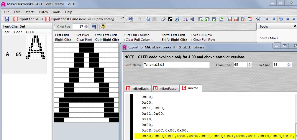
After playing around with different font generating programs I settled on GLCD Font Creator, you firstly import an existing font (i.e the Windows system fonts), choose the size and specify the ASCII codes for the characters you want. Once you are happy with the size, you “Export for TFT and new GLCD” and select “mikroC” then copy over the array contents.
uint16_t yArray = (location * 36);
for (uint8_t y = 0; y < 18; y++) {
	uint8_t charValue2 = pgm_read_byte(&numberArray[yArray++]);
	uint8_t charValue1 = pgm_read_byte(&numberArray[yArray++]);

	for (uint8_t x = 0; x < 8; x++) {
		if (charValue2 & 1<<x) {
		  Adafruit_SSD1306_drawPixel(x + xPos, y + yPos, WHITE);
		}
	}
	for (uint8_t x = 8; x < 16; x++) {
		if (charValue1 & 1<<(x-8)) {
			Adafruit_SSD1306_drawPixel(x + xPos, y + yPos, WHITE);
		}
	}
}

// Increment x
xPos += 15;
It breaks up the character in blocks of 8 going row by row starting at the top left so we can make ourselves a parsing function to display the character we would like, just make sure all letters match the 12×18 or 14×18 font I went with as some letter come out a bit bigger than 14 pixels wide. We have the x and y position as global variables and we increment the x after each character is printed. We’ll have to also print a dot for say “3.300V” text, so I just did that by hand.
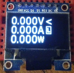
Now that the OLED screen works, we can have it print out the voltage and current in use and I have a [L] to indicate when we hit the current limit. We have 1 line free which could be used for displaying the power draw in watts or maybe we could use it to calculate the current drawn over time.
Just testing out the calibration function so that it only stores the digital pot / mosfet value that makes the ADC value change, it seems to work quite well. For the next part, I’ll put it all together on a PCB with the current limit and see how it goes.


