From the last part, we decided on our design – use a DC-DC to pre-regulate the voltage feeding into the LM350 linear regulator that’s controlled by a PNP transistor and we’ll use a N mosfet with op-amp for the current limiting. Now we’ll add in everything else – the displays, ADC, DAC and Digital pot, it’s taken a while to reach this point.
I started checking for the parts and came up with the following:
16bit MCP3425 I2c ADC ($3.1)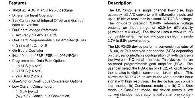
It has an on-board 2.048V ±0.05% voltage reference which is pretty nice. It does 15 samples per second at 16 bit, a bit low but it’ll work.
12bit MCP4726 I2c DAC ($1.4 x 2)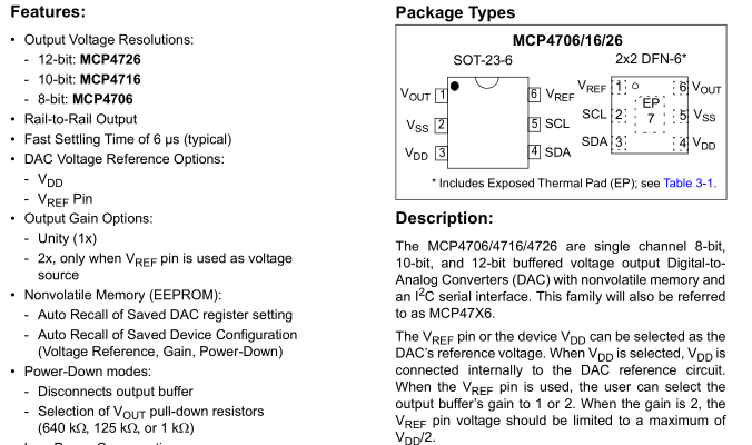
I like this DAC because you can either use VCC or any voltage from 0.01V as the reference voltage which can be buffered (could use resistor dividers to set voltage) or unbuffered. This is going to be very handy for setting the current which passes through the 0.1 ohm resistor. We will need 2x of this DAC, you can purchase different address options (can be harder to source).
10k 128-step MCP4018 I2c DPOT ($0.7)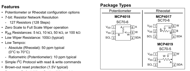
Originally I was going with the cheapest MCP4013 10K 64-step option (it’s a 2 pin Up/Down device) but later on I wanted to save wires going off to each device, so I switched to the MCP4018 which is I2C.
ATmega/Display/Buttons
The first part was to get the ATmega169A with 4 displays, rotary encoder and some buttons up and running along with some code for adjusting each number in different ways. The ATmega drives 2 displays with shared resistors directly which takes up 16 pins x 2 and the timer display refresh is set to 2 ms.
// Setup INT0 for rotary encoder
EICRA = (1<<ISC01); // Falling edge
sbi(EIMSK, INT0);
This time for the rotary encoder I have one pin hooked up to INT0 so we can configure it to interrupt us on a failing edge and then we just check if the other pin is high or low to see which one was low first to know the direction it was turned.
uint16_t ps1Voltage = 0;
uint16_t ps1Current = 100;
uint16_t ps2Voltage = 3543;
uint16_t ps2Current = 1251;
....
store_number(ps1Voltage, 1);
store_number(ps1Current, 2);
store_number(ps2Voltage, 3);
store_number(ps2Current, 4);
As I’ve done before, I’m using 16 bit ints to represent a double as it’s easier to work with, so 3543 would be 3.543V.
uint8_t SoftI2cMasterRead(uint8_t last, uint8_t TWI_SCL_PIN, uint8_t TWI_SDA_PIN) {
...
We’ll be driving 4 I2C lines, one for PS1 and another for PS2, so I quickly added for changeable pins for each I2C function.
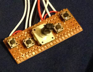
I’m trying out having 4 buttons of which 2 could double up as power supply enable which would either hook into the DC-DC power enable or just control a in-line mosfet. The closest buttons could allow us to blink 1 digit of the display so we can adjust the value and move on to the next digit, moving on from the last digit of the voltage takes us to the first digit of the next display. We can press the outer 2 buttons to stop and then we can adjust the rotary encoder for finer tuning of the voltage or current.
Adding the DAC
Now that the display works, we can add in the DAC, the first DAC will control the LM350 PNP transistor and the second DAC on the current limit, we will need to make a quick configuration change – set the reference voltage as the VRef pin.
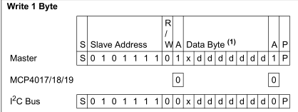
#define PS1_VSET_DAC_ADDR 0x60
#define PS1_CSET_DAC_ADDR 0x61
#define WRITE_DAC_REG 0

soft_i2c_write_2_bytes_no_addr(PS1_VSET_DAC_ADDR, WRITE_DAC_REG | ((ps1LMDac & 0xF00) >> 8), (ps1LMDac & 0xFF), PS1_SCL, PS1_SDA);
soft_i2c_write_2_bytes_no_addr(PS1_CSET_DAC_ADDR, WRITE_DAC_REG | ((ps1Current & 0xF00) >> 8), (ps1Current & 0xFF), PS1_SCL, PS1_SDA);
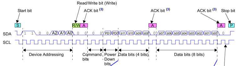
All we need to do is write the address (0x60/0x61), command bits as 00, power down as off (00) and the 12 bit number to set.
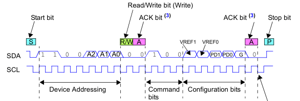
#define WRITE_DAC_CONFIG_ENABLE_VREF 0x98  // 100 command bits, 11 VRef, 00 power down bits (Not Powered Down), 0 Gain

// Set VRef on DAC used for current limiting
soft_i2c_write_byte_no_addr(PS1_CSET_DAC_ADDR, WRITE_DAC_CONFIG_ENABLE_VREF, PS1_SCL, PS1_SDA);
Enabling the VRef as the pin itself it easy too, just the address, command bits 100, Vref bits as 11, power down and gain bits as 0.
The first DAC will have the VRef as 5V so that gives us 1.22 mV steps and the current limiting DAC VRef could be as low as 200mV which would support up to 2A over a 0.1 ohm resistor, in that case, we could have 48.8 uV steps, which would equate to 500uA steps in current limiting. The only problem is that since we use ADC to read the voltage, is it worth having another ADC to read the current? For me, probably not at this stage, however another option would be use an good analog switch to switch the ADC input between voltage and current, it would be ~$0.30 more so that might be worth testing.
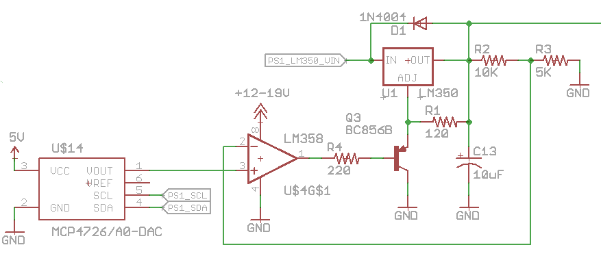
I tested the DAC on the LM350, with a value of 0 the output was around 2V and it took around a value of ~840 for the voltage to start increasing (we are losing 1/5 of our range). Once we go higher each increase of the DAC output results in 3-4mV of change on the LM350 output, so it’s not too bad at all.
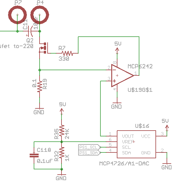
Next the current limiting DAC was tested, at a value of 0 it gave an output of 1.2mV which resulted in 15mA of current flow and the output started changing at a value of ~49 and increase by ~100uV each step after that. The minimum voltage output of this DAC is typically 10mV, if that was the case that’s no good for the current limiting circuit.
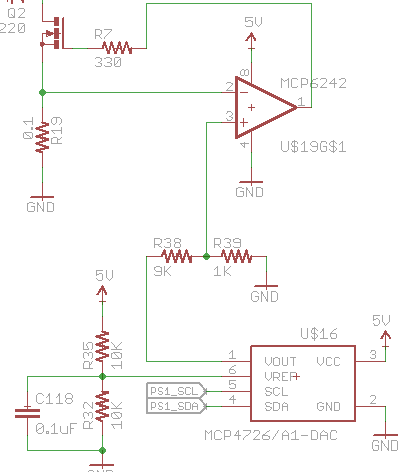
I checked the DAC on the LM350 which had the VRef as the power supply 5V, it gave an output of 1.2mV and 1 step higher it changed to 1.6mV. What we could do is increase our VRef from 200mV to 2V/2.5V and then apply a 10:1 resistor divider on the output, so the 1.2mV would be 120uV and equate to 1mA of current when the DAC value is 0 in theory. Now the problem is the op-amp, the input offset isn’t low enough to read the 120uV, so we receive ~10mA at a DAC value of 0, I’ll need to check out other op-amps.
Adding the ADC
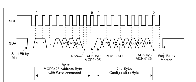
We have to setup the ADC to operate in 16bit mode and we may as well leave it running all the time instead of doing one shot. The ADC has differential inputs with a maximum voltage of ±2.048V so a resistor divider of 100K/15K will take care of us up to 15V and at 16bit we expect 62.5uV resolution. When taking account for the resistor divider, 5V before the divider gives 652.17mV after and 5.001V gives 652.3mV which would be detectable by the ADC but we have to account for some noise a few LSBs of noise too.
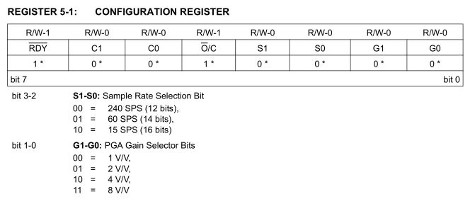
// Set ADC to 16bit
soft_i2c_write_byte_no_addr(PS1_VSENSE_ADC_ADDR, 0x98, PS1_SCL, PS1_SDA);
To enable 16bit mode we write S1-S0 as 00 in the configuration register.
soft_i2c_read_2_bytes(PS1_VSENSE_ADC_ADDR, PS1_SCL, PS1_SDA);
ps1Voltage = (uint16_t) (double) ((i2cAdcHighByte << 8) | i2cAdcLowByte) * (double) 0.0000625 * (double) 7.6 * (double) 1000;
We can read the 16bit value by reading 2 bytes from the ADC then multiple by the resolution, resistor divider number and by 1000 so it’ll be an int for displaying on the screen.
// Calibrate ADC resistor divider if PS1 and PS2 enable are both pressed at the same time
if ((PIND & (1<<PS1_EN_SWITCH)) && (PIND & (1<<PS2_EN_SWITCH))) {
	...
	inCalibration = true;
}
if (inCalibration == true) {
	ps2Current = adcResistorDivider;
	if ((PIND & (1<<PS1_EN_SWITCH)) || (PIND & (1<<PS2_EN_SWITCH))) {
		eeprom_write_byte((uint8_t*) ADC_RESISTOR_DIVIDER_EEPROM_LOCATION, adcResistorDivider >> 8);
		eeprom_write_byte((uint8_t*) ADC_RESISTOR_DIVIDER_EEPROM_LOCATION+1, adcResistorDivider & 0xFF);
	...
We’ll need to make the resistor divider number easily changeable so we can calibrate it compared to a multimeter, so I made it if you press PS1 and PS2 enable together it will show the calibration value (e.g 7600) which you can adjust with the rotary encoder and then we save it to the EEPROM.
Adding the Digital Pot
With the LM350 we want to keep the input voltage about 2V to 3V higher on the DC-DC converter for some headroom when using drawing a few amps , so that would mean 5V minimum and 19V maximum.
soft_i2c_write_byte_no_addr(PS1_DCDC_VSET_POT_ADDR, ps1DcDcVoltDPot, PS1_SCL, PS1_SDA);
The MCP4018 is easy to control, just write a byte with the 7 bit value.
uint16_t ps1AdcAvg = 0;
for (uint8_t x = 0; x < 10; x++) {
	adc_start(PS1_DCDC_VSENSE_ADC_PIN);
	_delay_ms(1);
	ps1AdcAvg += adc_result();
}
ps1DcDcAdcVoltage = ps1AdcAvg / 10;
ps2Voltage = (int) (double) ps1DcDcAdcVoltage * (double) 0.00107421875 * (double) 21.06 * (double) 1000;

int16_t voltageDiff = ps2Voltage - ps1Voltage;
if (ps1DcDcVoltDPot > DCDC_POT_MIN && voltageDiff < 2500) {
	ps1DcDcVoltDPot--;
}
else if (ps1DcDcVoltDPot < DCDC_POT_MAX && voltageDiff > 3500){
	ps1DcDcVoltDPot++;
}

soft_i2c_write_byte_no_addr(PS1_DCDC_VSET_POT_ADDR, ps1DcDcVoltDPot, PS1_SCL, PS1_SDA);
Now that we can control the DC-DC output voltage, we’ll need to adjust it every now and then. At first I tried to adjust it every 50ms but found that it was jumping around quite a lot so I reduced it to run every ~500ms. I’m using one of the ATmega’s ADC pins (with 100K / 5K resistor divider) to read the voltage to know if we are between 2.5-3.5V above the LM350 output. Since I don’t go to ADC sleep mode the ADC readings won’t be the best so I’m using 10 averages 1ms apart and the DC-DC voltage for debug shows on PS2 display for voltage.
while (settingVoltage == 1) {
	soft_i2c_write_2_bytes_no_addr(PS1_VSET_DAC_ADDR, WRITE_DAC_REG | ((ps1LMDac & 0xF00) >> 8), (ps1LMDac & 0xFF), PS1_SCL, PS1_SDA);
	_delay_ms(70);

	soft_i2c_read_2_bytes(PS1_VSENSE_ADC_ADDR, PS1_SCL, PS1_SDA);
	ps1Voltage = (uint16_t) (double) ((i2cAdcHighByte << 8) | i2cAdcLowByte) * (double) adcResolutionLsb * (double) (adcResistorDivider / (double) 1000) * (double) 1000;

	int16_t difference = voltageSet - ps1Voltage;
	int16_t adjustment = 0;

	if (difference > 1000) {
		adjustment = 300;

		// Boost DC-DC voltage by a bit
		if (ps1DcDcVoltDPot > (DCDC_POT_MIN + 5)) {
			ps1DcDcVoltDPot -= 5;
		}
	}
	else if (difference < -1000) {
		adjustment = -300;
	}
	...
	else {
		settingVoltage = 0;
	}

	// Check we can adjust the DAC to the level required, else exit
	if ((ps1LMDac + adjustment) > 0 && (ps1LMDac + adjustment) < 4095) {
		ps1LMDac += adjustment;
	}
	else {
		settingVoltage = 0;
	}

	dcdc_regulate_voltage(0);
	...
When the voltage is adjusted via the blinking digit way, we could go from say 2V to 7.5V so adjusting the DC-DC digital pot every 500ms would be too slow so I made a function for this purpose – compare the output voltage of the LM350 to the desired voltage and adjust. If the voltage set is more than 1V higher, we add some extra Dpot value to increase the DC-DC voltage more as it can take a while for it to respond.
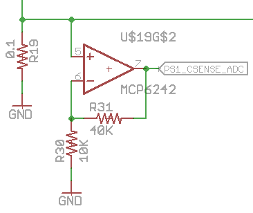
For the detecting the current flow I’m using the ATmega once again, we have a spare op-amp channel so we can use a 4x multiplier so for a 5mV drop of the 0.1 ohm resistor it would give 25mV which is enough to cover all the 2 amps range up to 1.1V (so we can keep using that as the voltage reference on the ATmega).
Download Dual_PSU_Dev1 (kind of a mess at the moment)
For the next part, I’ll try using a different op-amp, test out the 16bit ADC to measure the current to see if it’s worth it with the analog switch, check whether an in-line mosfet to switch the power on and off is worth doing, clean up the code, determine whether it’s worth using thermistors to measure the heatsink temperature to switch off the power supply if it’s too hot and maybe look at laying out the board.


