A while back I made a Small Programmable Power Supply which at first was going to have a P mosfet to control the voltage but I switched to a LM2596 DC-DC when I found the mosfet was getting too hot. The power supply has worked well for me over the past few years but now it’s time to build something better. One of the problems with the old power supply was that when you got to the higher end of the voltage range (6V+), there were big jumps in voltage (0.2V-0.5V) when you turned the knob higher, this is because of the digital pot and resistor divider used to adjust the voltage.
At first I was thinking of doing a 3 output power supply, each output would have their own dedicated DC-DC however upon testing the Richtek DC-DC that I’ve used before with the digital pot, I would still run into the same problem. What we could do is stick a linear regulator after the DC-DC and give it 2-3 volts headroom which would save us from having the linear regulator drop all the voltage on it’s own. I’m currently testing the LM350 which is similar to the LM317 but can handle at least 3 amps and allows for voltages of 1.2V to 33V, I’ll be looking at powering this supply from a 19V power adapter so I could have a voltage range of 1.2V to 15V or so.
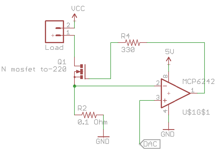
I would also like to add current limiting to the power supply and to see how much current is being drawn by the device under test, I’m looking at either 2 or 3 amps. We can re-use the constant current dummy load circuit and by placing the load before mosfet, the op-amp will regulate how much current will flow through the mosfet. One problem I’ve found is when you hit the current limit, the mosfet is in the linear region just like in the dummy load so it gets really hot. I thought I could get away with a small mosfet without a heatsink but I was wrong, I’ll have to go with a TO-220 style with a decent heatsink. On the other hand, if you did want go with a small mosfet, you could detect that a current limit occurred and then turn off the output.
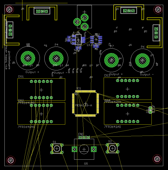
Above is a rough look at what it could look like (10x10cm). I’m looking at having 2x of 4 digit LED displays, one for voltage and one for current, the same rotary encoder like last time and having the power supply be dual output. Two push buttons on either side of the encoder would select the the voltage and then another push for current, the LED display has a little dot light at the bottom right so this could be used to indicate which display was being set or I could add 2 LEDs on either side of the display. No need for shift registers any more as I’d be using an ATmega169A which has enough pins to drive the displays directly.
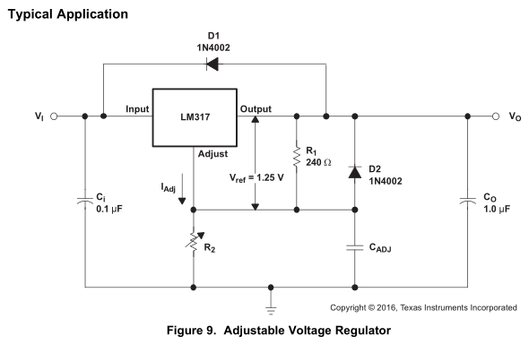
The LM350 like the LM317 has an adjustment pin from which current is sunk through a resistor to ground, we could stick a digital pot there however once we approach higher voltages we would need to use a high voltage pot.
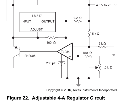
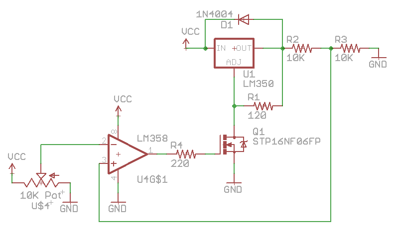
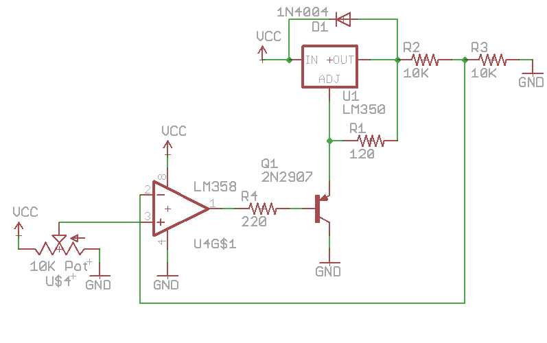
Further in the datasheet there is an example of an adjustable regulator (they had 3x LM317’s in parallel) but we can see that by using an op-amp with an PNP transistor we can set the voltage via the 1.5K resistor as the PNP will be sinking the adjust current. I found a related post on the EEVBlog forum which shows that by placing the PNP collect to ground we can then digitally control the op-amp via the non-inverting with a DAC or similar.
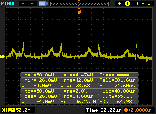
I tested the circuit out with an LM358 op-amp and MPS751 PNP and it does seem to work well, voltage output noise shown above from a perfboard using the oscilloscope ground lead. The output voltage isn’t adjustable all the way down to 1.25V which is partly due to the PNP CE diode voltage drop and also a bit due to the fact the LM358 isn’t a rail to rail op-amp. On a 5V input to the LM350, I see 2.5V on the output and 0.6V on the base. For 4.1V output, I see 3.7V on the base.
With a rail to rail op-amp like the MCP6242 (5V Vcc max), I see a 1.9V output and 0V on the base however it’s not a good idea to use it if we set the output to say 7V as the op-amp will try to output 6.25V (output minus 1.25V) so a high voltage op-amp is needed. We could add a resistor divider to the op-amp’s output for the LM358 and that would allow us to drop the voltage a bit lower which would affect our top end if we stayed on 5V Vcc however if we powered the LM358 from the 19V input supply which I will likely do, then the top end won’t be a problem.
I tried using a P mosfet instead of the PNP transistor however it wasn’t any better, must have been that Vgs wasn’t high enough.
It’s clear that the easiest solution will be with a N mosfet since we don’t need to worry about the LM350 putting voltage on the source (as it’s now ground), swap over the non-inverting with the inverting on op-amp and it tested out nicely even with LM358’s non rail to rail output because the Vgs of the N mosfet is around 1-3V.
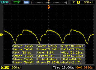
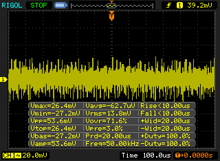
However, when testing the N mosfet, there is some switching noise (left), we can see the output of the op-amp has a large swing to it too (right), the feedback resistors (10K/10K) also had it (not pictured). It gets worst when you apply a load of 68 ohms.
So it looks like it’s back to the PNP solution which works much better (10K pot is just for testing).
This raised a question for me, instead of the digital pot for the DC-DC, could you use a PNP? Yes it looks like you can, though there is only a small window between 270mv to 300mv on the base (through a 220 ohm resistor) that changes the DC-DC output voltage when using a 24k resistor in the top half of the resistor divider. The N mosfet works too but the window is even smaller, for the DC-DC I think I’ll go with the PNP. It’s just a matter of convenience and lower part count if you went with the digital pot, though it’s like $1 a pop so I think I’ll go the PNP method + op-amp instead. Edit: Don’t think I actually thought it through, I wouldn’t have a way to control the op-amp unless I used a DAC or some resistors, so I will be going back to the Digital Pot, plus I found I shouldn’t need much range and can pick up a 10K one 64 steps for 70c.
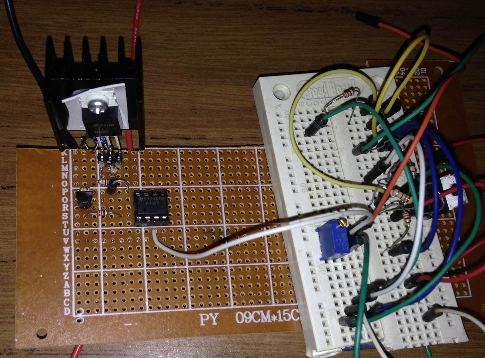
(testing the LM350)
So for next time, I just have to combine it all together and test it a single channel – DC-DC, linear regulator, current limiting and add on a DAC to control the linear regulator op-amp, a digital pot for the DC-DC pre-regulator and test out the displays with the ATmega. The DAC will likely be a 12 bit one and I’m thinking I will need to use a 12 or 16bit ADC as the 10 bit on the ATmega might be too low to give the resolution I would like.


