I thought that it’s about time I purchased or made an easy to adjust power supply as all I have at the moment is the LM2596 power supply module from Ebay; one problem is that it’s hard to adjust the 10K pot as you need a screwdriver and another is that it’s not programmable.
(sneak peak)
I’ve chosen the build it yourself route as I don’t think I’ll need more than 1 amp of current. I could just use a computer power supply however I want it to be a bit smaller than that. Another feature I’d like is to be able to program voltages to different buttons.
First off, potentially we could adjust the LM2596 using a 10K digital pot however if you wanted voltages more than 5.5 volts then that won’t work out as the digital pot (MCP4017T) I’m using has a maximum voltage of 5.5 volts. If you wanted 0 to 5.5V this would work but I want up to 12V. You can buy digital pots with higher voltage range however they are like $9 each. A quick way around this is to use a resistor divider (like 330 ohm / 10K pot) and use that on the feedback loop however testing this only resulted in a minimum voltage of 2.6V. Depending on the first resistor, when adjusting the pot it lead to a high or low amount of voltage change (e.g 0-5K would only change 1V), so this won’t work out.

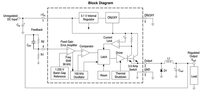
I happened to find a document on LDO Regulators and there was an circuit with a P Mosfet with an op-amp and the ability to set voltage reference – the op-amp is constantly adjusting the output compared to the feedback and voltage reference. I’d like a range of 1.8V to 12V, the op-amp should be able to handle that too – an LM358 should do the trick with its 36V max input voltage.
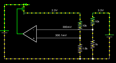
We would have 12 – 15V input from an AC adapter and a 3.3V regulator to connect to the voltage reference with a 10K / 10K digital pot resistor divider so the maximum voltage the digital pot would ever see is 3.3V. After some quick simulation a 10K / 1.5K divider for the inverting input works best to give about a 200mV change for every 100 ohm change in the digital pot.
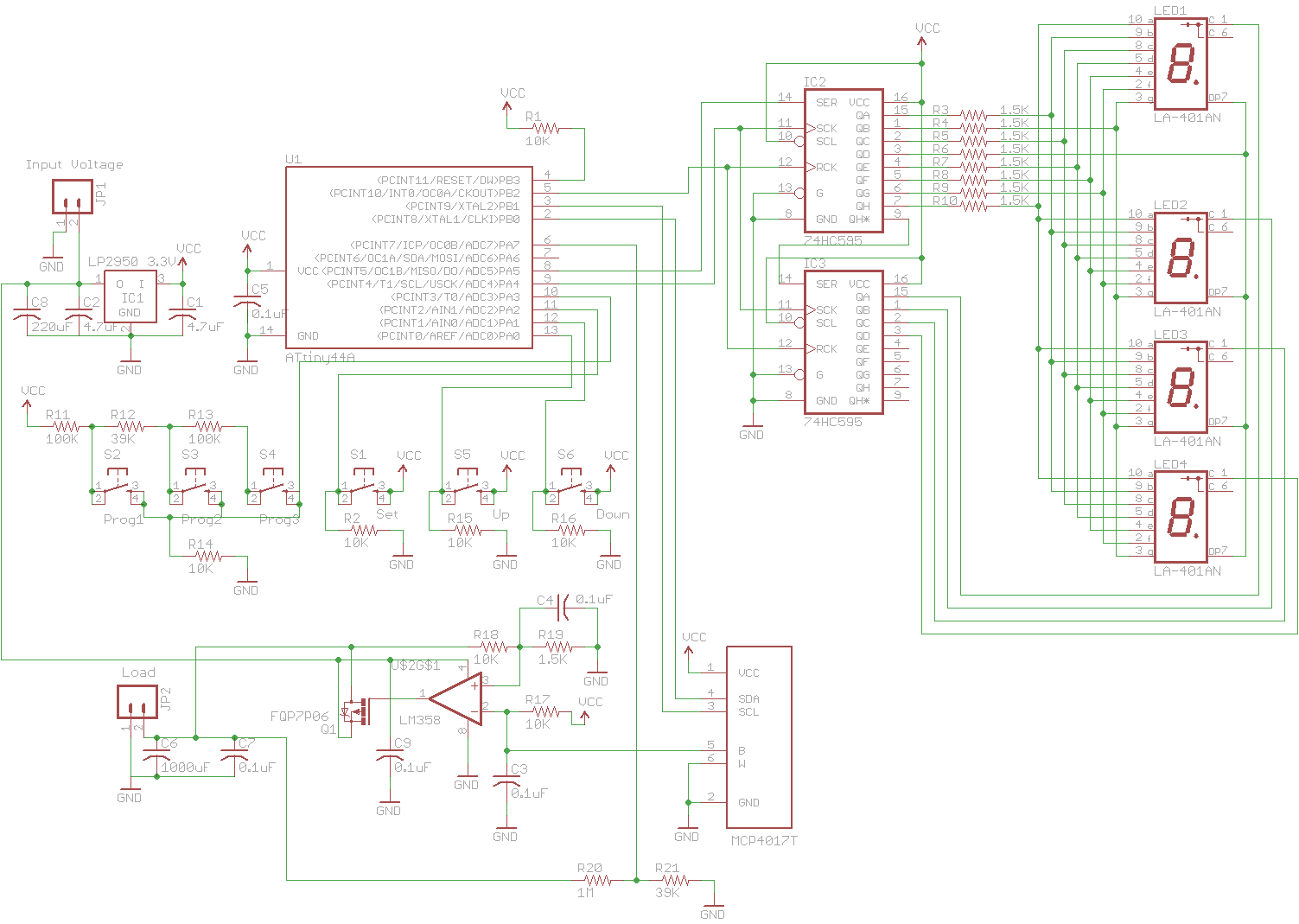
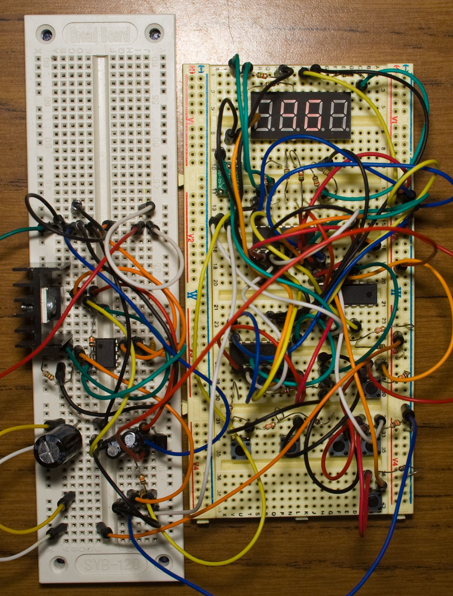
Here’s our schematic – A 4 digit segment display using an ATtiny84 with 2 shift registers can be used to display the voltage with the last segment that can be used to show which programmable present we are running. A 1M / 39K resistor divider can be used to read the voltage output and use the ADC to check which of the 3 programmable buttons were pressed by connecting resistors in-between each button. We can have a button to program the 3 buttons and two more buttons to set the voltage higher or lower.
.
The Code
Normally the way I would do the code is to have it shift out to each led segment and then delay for a few milliseconds and do them all at once. I found doing this and other things in the main code such as reading the ADC a few times could sometimes cause it to flicker ever so slightly, so now I use a timer to call the function every 2 ms to each segment.
// Read voltage
if (readADC == 0) {
  int adcValue = analog_read_average(adcPin, REF1_1V);
  double calculateDouble = (double) ((double) (adcValue) * 1.074) * 0.027015; // Calibrate this for higher accuracy
  store_number(calculateDouble);
  readADC++;
}

// Read saved buttons: 3.3V - B1 100K - B2 39K - B3 100K and 10K to GND
int adcValue = analog_read(adcButtons, REF1_1V);

// First saved button ~300mV
if (adcValue >= 260 && adcValue <= 300) {
  action = 10;
  actionCounter = 255; // Leave on the LED on
  programButton = 0;
  dpotSetting = eeprom_read_byte((uint8_t*) programButton);
}
// Second saved button ~221mV
else if (adcValue >= 185 && adcValue <= 225) {
  ...
}
// Third saved button ~132mV
else if (adcValue >= 102 && adcValue <= 142) {
  ...
}

// Read set button
if (PINA & (1<<PA2)) {
  action = 5;
  actionCounter = 100;
  eeprom_write_byte((uint8_t*) programButton, dpotSetting);
}
// Voltage up or down button
else if (PINA & (1<<PA1)) {
  if (dpotSetting < 127 && (buttonCounter == 0 || buttonHeld > 10)) { // If held down, increase voltage quicker
    buttonCounter = 150;
    if (buttonHeld <= 10) {
      buttonHeld++;
      dpotSetting++;
    }
    if (buttonHeld > 10) {
      buttonHeld++;
      if (buttonHeld % 10 == 0) {
        dpotSetting++;
      }
    }
    dpotDisplaycounter = 250; // Display the digital pot estimated value for a little while
    double dpotTemp = ((3.3 / ((dpotSetting * 0.078) + 10)) * (dpotSetting * 0.078)) * 7.66;
    store_number(dpotTemp);
  }
}
else if (PINA & (1<<PA0)) {
  if (dpotSetting > 0 && (buttonCounter == 0 || buttonHeld > 10)) {
    ...
  }
}
else {
  buttonHeld = 0;
}

// Write value to digital pot
soft_i2c_write_byte(pot_address, dpotSetting);

// Used for timing so that button presses don't trigger more than once every half second or so
if (buttonCounter > 0) {
  buttonCounter--;
}
...
// Timer0 overflow after 2ms
ISR(TIM0_OVF_vect) {
  display_led(numberDisplay[0], numberDisplay[1], numberDisplay[2]);
}
After our usual setup of the inputs, outputs, ADC, etc we read the voltage every 250ms and display it on the first 3x 8 segment displays. We read the ADC to see if any the 3 programmable buttons and then if any of the other buttons were pressed, we display what the digital pot value in voltage would be briefly then write the value to the digital pot.
The display_led function just shifts out the number to each segment, the fourth segment is the indicator of which programmed button was pressed or when the set button is pressed. There is also a action counter which allows us to display items on the forth segment for a specific amount of time.
Download SPPS_v0.1
.
Testing
Here’s a few tests I’ve performed on this power supply, some were performed with no capacitors on the op-amp and some of the later ones were so we can see a difference. One thing I have noticed is that when you adjust the output to say 12 volts and then drop it down to say 3 volts, it does take a few seconds for it to adjust the voltage down, this is because of the output capacitor being 1000uF. Edit: Adding a load resistor of 1.5K to the output seems to sort this out.
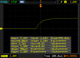
Switch on to 3.3 volts, no overshoot as far as I can see.
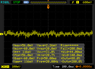
Noise with no load at about 7 volts.
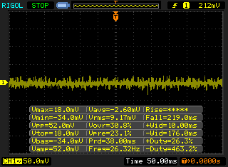
Now with more capacitors.
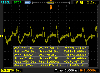
With a 12V 0.57A fan at 7V with a 1000uF output cap, a bit noisy.
With the same fan running at 12V.
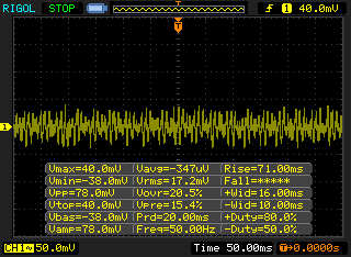
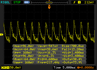
Now running at 7V with 2000uF output cap, a bit lower Vpp than the 126mV before.
When testing with the 12V 0.57A fan, the P Mosfet does get pretty hot, so I had to stick a heatsink on it, I get 42C on the heatsink with 22C ambient. Apart form that, as per the video at the start, it works well to my requirements.
A few improvements that can be made:
- 128 steps for the digital pot might not be enough, we can buy a 256 step digital pot for not much more
- We could use a rotary encoder instead of the buttons for changing the voltage
- We could use a relay to switch on the output when the voltage selected matches the actual output voltage – i.e is stable
Part 1
Part 2: Added rotary encoder and more testing
Part 3: Back to the LM2596 and calibration
PCBs arrived
Small Programmable Power Supply v1.0 Released


Do you think you will create a PCB from your design? This seems like a solid design and would like to have one for myself. Perhaps a batch PCB order and you can sell the extra boards?
Hi Dillion, yep I’ll be creating a PCB but before I do I’d like to test out using a rotary encoder and a higher resolution digital pot, so it might be 2-3 months before the PCB is ready.
[…] His design is based around the LT3080 but has a constant current control loop. Here is an example with an explicit regulator (part 2, part […]