A while ago I built a simple constant current dummy load for testing my SMPS however the maximum load was about 1 amp and 2 amps with a fan on it and I always had to use a multimeter to measure the current. I’m looking at having a load of up to 4 amps or more, adding an ATtiny to control a 4 digit LED display to show the current, use a proper potentiometer and use a bigger heatsink.
https://www.youtube.com/watch?v=tWYfkr0ul5w
Originally I was planning to have it all powered by input voltage like before however at low voltages the STP22NF03L N mosfet that I had lying around didn’t switch on enough with the MCP6242 op-amp so after thinking about how I could do it – use 2x coin cell batteries, 9V battery, etc, I went with a Lipo battery. An upside of using a battery is that this allows us to use any input voltage between 0V to 30V to test our load with.
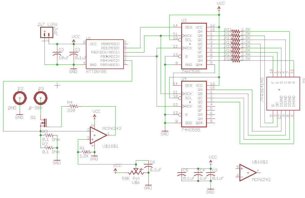
Before I had 1 ohm resistors which were almost getting as hot as the mosfet so I’ve gone down to 0.1 ohm 3W resistors – I added the option of another resistor in parallel if need be. I used a 1.5K resistor on the op-amp on the non-inverting side of the op-amp for a bit more fine tuning of the pot.
I had some previous code for controlling the 4 digit LED display so it was the easy part and then we’ll just use the ATtiny’s ADC to measure the voltage drop on the resistor. Download ADC_to_4_Digit_LED_Display_v1.0 and CCDL_with_4_Digit_LED_Display_v1.0
There used to be a 0.1uF cap on the drain of the mosfet but I found it made things worst – there was oscillation and the current load would randomly change anywhere between 2 to 5 amps. One problem with our design is that when no load is connected the op-amp output will be at the maximum until a load is applied, so there will be a small current spike at the start.
After a little bit of calibration, I was able to get it with-in 20-50mA of the real current, the maximum current was 8.5 amps with the multimeter in series but once it was removed it got up to 9.9 amps.
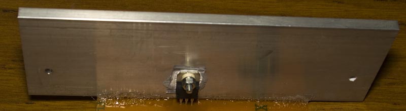
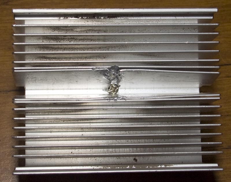
For the heatsink, I went with what I thought would be a good size but it wasn’t good enough in terms of temperature, so I grabbed an old CPU heatsink drilled a hole and cut/moved some fins out of the way for the screw – it took a while but it’s very nice now.
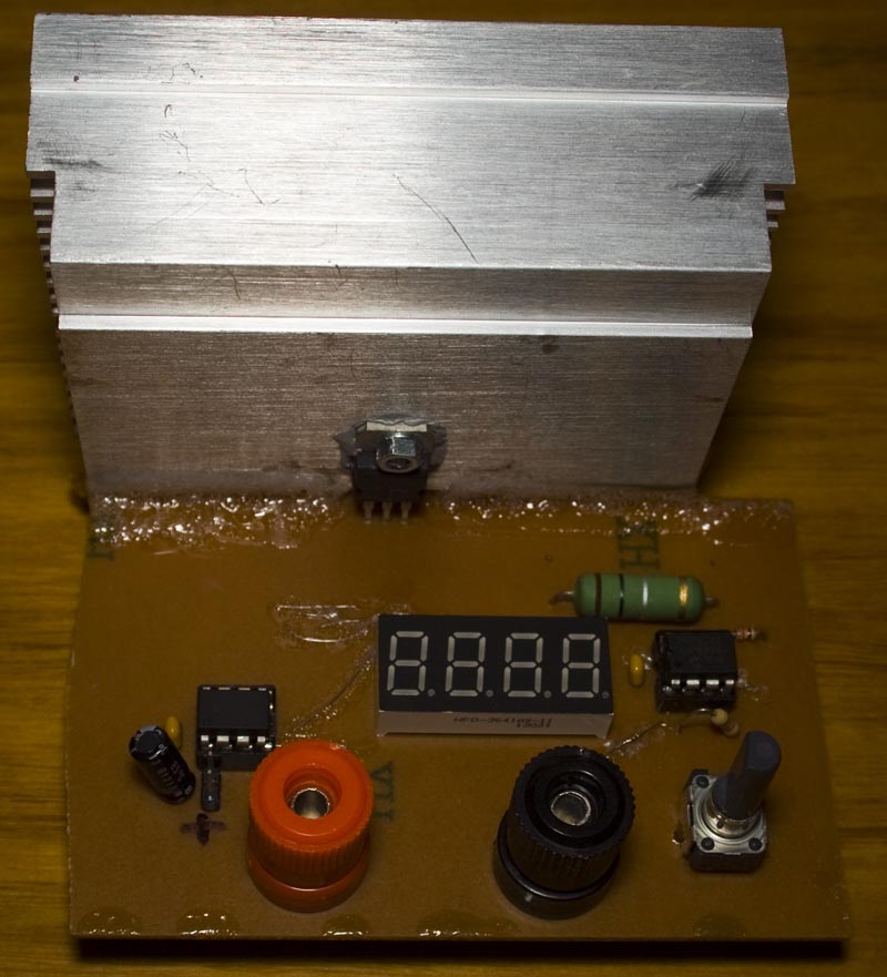
When testing with the new heatsink at 5 volts at 3 amps and 29C ambient – the mosfet got to 50C, 0.1 ohm 3 watt resistor was 82C resistor. I changed the resistor to a 5 watt ceramic and now I can go up to 4 amps with 55C on the mosfet and 82C on the resistor. I might change the resistor to a 0.05 ohm 5 watt so it’s still high enough voltage drop for the ADC to get a good reading and may add another resistor in parallel to see how much I can draw before the mosfet gets to 70C or so but apart from that everything works great!


Interesting regarding the current spike. I haven’t tried this myself but here goes, and I’m planning to test this myself.
If the regulator needs current to stay in regulation at all times it needs to see some current when the source is disconnected from the terminals. The answer would be a current source connected to the drain of the mosfet I guess. For example lm334 programmed to 1mA. I saw this in the uSupply.. Not sure how well this technique will apply in a dummy load though.
Dave Jones’ uSupply:
http://www.eevblog.com/projects/usupply/
Undeniably believe that that you said. Your favourite justification seemed to be on the internet the simplest thing to bear in mind of.
I say to you, I certainly get annoyed at the same time as
people think about issues that they plainly do not realize about.
You controlled to hit the nail upon the top and also defined out the entire
thing without having side effect , people could take a signal.
Will likely be again to get more. Thanks