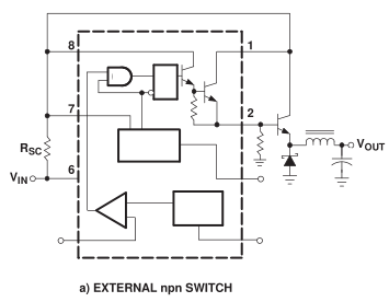
From our last post we looked at adding a transistor to the MC34063 and eventually changed to a P mosfet although we had to use a pretty large heatsink to dissipate all the heat. I decided to revist this SMPS to see if we could improve it to generate less heat, as I might have a few projects that could possibly use 5V output and 12V+ input.
I decided to build the circuit with a NPN transistor – the TIP31 however with a small heatsink with 5V @ 0.37A, it rose up to 55C so I went back to a P mosfet. I began changing all the other parts – using different diodes, inductors, resistors however the P mosfet still got pretty hot even with a small heatsink.
Thinking that the MC34063 could be causing the issues itself, I went ahead and used an ATtiny to replicate what a little bit of SMPS would be doing – pulsing an output high and low for a specific duty cycle until I reached 5V. The heat was about the same as the MC34063 but just a little less as I didn’t compensate for the load reducing the voltage.
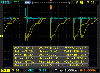
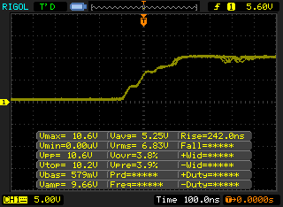
So it’s back to the IRF9540 P mosfet, after researching into it, it seems like the turn off time / capacitance is pretty important for our application, this mosfet has 1400pF input / 590pF output capacitance, 73ns rise time, 34ns turn off and 57ns fall time. On paper this mosfet seems good however as above we can see the turn off time is really 4us (yellow line, going low to high). Also there is an spike (blue) which I was able to soften down later a bit by adding a 470uF capacitor to the input VCC/GND (before I had 100uF).
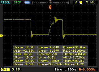
I switched to the FDC365P P mosfet which features 55 milliohms Rds with 530pF input / 150pF output capacitance, 10ns rise time, 28ns turn off and 10ns fall time – you can see that this has helped the turn off time to about 700ns
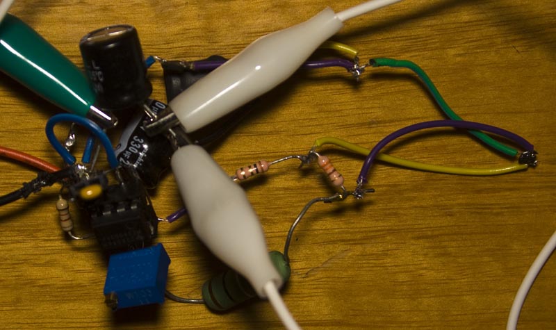
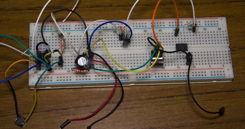
This has corresponded to a mosfet that now gets less hot, when the part is in free air, 0.5A makes it 38C and 0.9A is 68C, 1A is 78C. Above is how it all looks at the moment. As you can see above, we do have some ringing when the gate goes high (P mosfet off) but it turns out that’s because I had the 220 ohm resistor tied to the 0.1 ohm instead of VCC, that’s now reduced the ringing.
We can make the P mosfet turn off quicker by added another 220 ohm resistor to VCC, now it only takes 250ns to switch off and this now means that at 1 amp it reaches 66C.
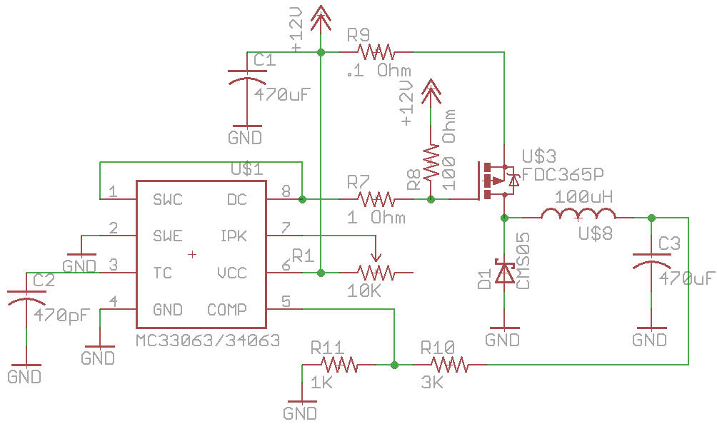
Here’s the schematic.
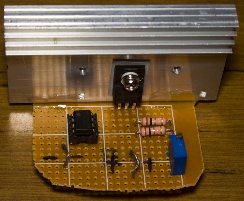
In order to test this power supply, I decided we’ll need an easy way to adjust the load. Using Dave’s constant current dummy load I was able to build it up with the parts that I had – a 10K pot, LM358, low Vgs IRLIZ24N N mosfet and a decent heatsink.
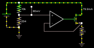
Whatever the opamp sees on the non-inverting input it does whatever it needs to do on the output to make the inverting input match, in this case 80mV equates to 80mA flowing through the mosfet. I added another 1 ohm resistor so instead of being a 1:1 mapping it’s now 1:2 because the LM358 isn’t a rail to rail opamp and now I can achieve close to 1 amp of current draw.
So that’s it, I’ve now got a SMPS that generates less heat and could potentially be used in a next version of my Small programmable power supply.
Part 1: Testing the base circuit configuration
Part 2: Adding an external transistor
Part 3: Revisiting and testing with a constant current load
Part 4: Trying another DC-DC – the Richtek RT8293A, testing PCB/breadboard and load/transient test against an Ebay $1 DC-DC


You can still make your P-channel MOSFET turn off considerably faster than this by the use of a diode, BJT and resistor.
Take a look at figure 22 in https://www.fairchildsemi.com/application-notes/AN/AN-558.pdf
You’ll need to turn it upside down obviously – change diode direction, swap PNP for NPN.
This is a very handy scheme to have in your repertoire, and suits the use case with an MC34063 perfectly, as the output transistor of the 34063 can turn the FET _on_ fast, but not off.
Thanks, I’m going to have to give that a try soon
After trying the circuit, I’m seeing 92ns rise times which now leaves the mosfet at 39-40C when drawing 1 amp (30C ambient and the 220 ohm 1W resistor gets to 44C), so looks like that circuit is the way to go, thanks again!
Edit: I tried this circuit with the IRF9540 and got 134ns rise time and it tested ok, so now I should be able to use the TO220 mosfets without any overheating issues. Also the 0.1ohm resistor could be removed.
Thanks for sharing this. Can I ask, why does the rise/fall time of the FET/BJT influence power loss?
It’s because when the gate is rising or falling the FET/BJT is not fully on or off, it’s in the linear region which is when the internal resistance between drain and source begins to increase or decrease.
For example, if you had a 5 ohm load at 5V with a mosfet, if you turned the mosfet on or off slowly, imagine the resistance slowly changing for 10’s of Megaohms to say 40 milliohms (depends on the mosfet). At 100 ohms Vds resistance it would dissipate 226mW, at 10 ohms it’s 1.1W, 5 ohms is 1.25W and then when it passes that, the dissipation becomes lower, 1 ohm is 694mW, 40milliOhm is 49mW. With higher current loads this becomes more important but you can see that you want to turn it on or off as fast as possible.
You can use Circuit Simulator to see what it would look like, just stick 2 resistors in series, one will be your load and the other which you will test changing the resistance will be your mosfet.
Thank you very much for sharing this helpful article. gaming cpu