From our last post we looked at the base configuration of a SMPS using the MC34063. In this part we’ll look at adding in an external transistor so that we can bypass the 1.5A peak current limit present on the MC34063.
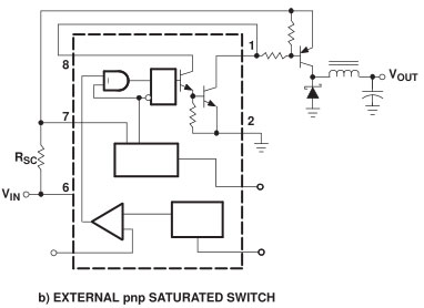
Above we have the circuit configuration which we can add our PNP transistor on, I’m using the TIP42C.
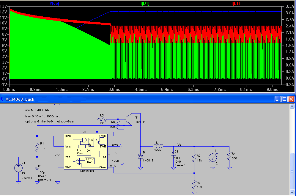
(Voltage – blue, Current though diode – green, Current though inductor – red)
We can test this configuration on LTspice, though one problem when using the transistor is that it gets very hot. For testing I’m using two 100 ohm resistors, so it’s quick to switch on and off. We need an inductor and diode that can handle the current because the 1N5819 diode only can do 1.5A so I choose the Toshiba CMS05-TDE which can do 5A and only has a 0.45V voltage drop. I was able to salvage a decent sized inductor from an ATX power supply.
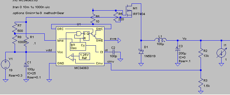
Let’s switch to a P mosfet, the IRF9540 in this case (was $1 last year but now it’s double the price), it has a 0.2 ohm on resistance and can handle 19A. After lots of testing, I’m changing the resistor configuration to switch it on fast with a 10 ohm resistor and then switch it off not that quickly with a 220 ohm resistor. Download mc34063_buck_mosfet
Upon testing this configuration (without the 0.5/10K resistors as pictured), for some reason, if the Isense current line was put after the 0.1 ohm resistor like it should, the expected current wouldn’t flow, only about half or less would and adding more 0.1 ohm resistors in parallel didn’t help. When changing to 3-4x 1 ohm resistors everything seemed to work fine.
By adding a 10K potentiometer (0.5/10K resistors represents this), we are able to adjust the Isense current which ends up changing how much current flows through our load and we can stick back to our 0.1 ohm resistor.
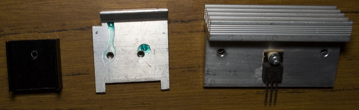
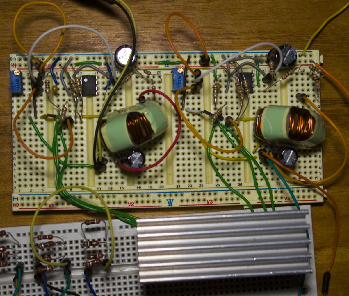
Our configuration above works fairly well however heat is still an issue, in an attempt to remove heat I’ve started beefing up the heatsink, salvaged once again from a old ATX power supply. Running from a 19V supply and having an output as 12V at 2.5A, we reached 60C on the left heatsink, 50C on the middle and 40C on the right. Since I’ll be using the 1 heatsink for the 2 mosfets, I’m using a small plastic tab to mount the heatsink too so that there is no electrical connection between the mosfets and the heatsink, later on I switch to a thermal pad which gave 2-4C improvement.
However upon testing this with a 5V output and 2 amps, I had temperatures of 70C and higher so something wasn’t right. After what seems a long time investigating, changing circuit configurations, etc, I found that the breadboard I was using had some heat related issues. I saw something glow red a bit and then the mosfet temperatures increased quickly to 170C. I moved the mosfets closer to circuit and the issue went away, so once again another reminder to myself to be careful with what you use breadboards for.
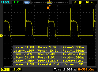
When we’re adjusting the 10K pot for the current, to some degree we are slightly changing the frequency of the mosfet turning on and off. Above we have the mosfet’s drain show, switch on time is around under 400ns (ignore the 6us) and 2 us switch off. Another way to change the frequency is changing the timing capacitor, having the right frequency can also determines how much current you send to your load and operating at too high frequency can mean that more heat is generated at the mosfet so I’ve changed my timing capacitor to 1000pF.
Testing with 4 hard drives had no issues, I was only seeing 0.7A on the 12V rail and 0.6A on the 5V rail whilst idle, mosfet temperatures were steady at around 40 to 42C on the big heatsink together at 30C ambient. The diodes get to about 45-50C and the 330/470 ohm 1/4W resistors I’m using for the mosfet turn off can reach 70-80C so I’ll need 1/2 or 1W ones for those and think about upgrading the diode too. I would like to build it on a PCB/Veroboard and leave it running for 24 hours before I’m sure that everything is working good.
Part 1: Testing the base circuit configuration
Part 2: Adding an external transistor
Part 3: Revisiting and testing with a constant current load
Part 4: Trying another DC-DC – the Richtek RT8293A, testing PCB/breadboard and load/transient test against an Ebay $1 DC-DC


Why not an NPN transistor? The arrangement is simpler and I can’t see any downside.
I recently modded a cigarette lighter USB charger based on this chip with an TIP41C NPN transistor, a heavier inductor and diode. Although for the higher current the inductor is only 18uh. I only had to cut one trace and wire the transistor and diode off the board. I did substitute larger filter caps, and a lower value current sense resistor (.25W at half the resistance for a peak of about 1.5A continuous). It may sound ugly, but even with a small heat sink I was able to fit it all back in the original case. I did use an 8k resistor on the transistor base to discharge it for faster switching and less heat. I tested it with an old mp3 player, and when it worked fine, I charged my phone with it. It generated less heat than it did before I modded it, so I’m thinking about dropping the value of the current sense resistor to get an output of about 2200mA (to 0.04 ohm, currently 0.06, was 0.12).
I used the ‘a’ schematic from TI’s data sheet, on page 8.
Hi Charles,
I guess I just saw the PNP / P Mosfet used more so I went that way, it seemed to make sense, but the NPN way like you’ve done would also work. But you bring up an interesting question, which way is better? The NPN way would have a voltage drop of 0.7V x 3 where was the PNP way this wouldn’t matter. I might test both ways and see which way is better.
I decided to re-visit this – I used a TIP31A NPN with 12V input, 5V input, 330 ohm from base to ground, 100uH inductor, running a computer fan (total draw of circuit 370mA), it got to 55C with a small heatsink (4cm x 3cm).
I changed the circuit configuration back for the P mosfet using IRF9540, 10 ohm to gate, 330 ohm to source, ran the same load without a heatsink and it got to 50C.
Do you really need to connect pin 7, I dont need current regulation , can you tell me if you dont connect pin 7 will the circuit still work and can you use instead PNP transistor the MOSFET IRF540 I need at least 10 A input current and sorry for the bad english
Hi Marko,
I’ve just tested the MC34063 on a standard configuration and yes you do need to connect pin 7, if you don’t then you get 0V output. You could potentially just connect it to VCC but as you say you won’t have any current limiting – I haven’t tested what other issues it could have, e.g. like unable to start a high current load, as always test everything out. The transistor would work, but you would need a really large heatsink on it unless you pick a top of the line transistor.
Ok, thanks will the efficiency be very affected?
hey Alex!
nice job! have you tried multiple MOSFETs in order to solve the temperature issue?
i mean in parallel. although it makes the circuit a bit complicated.
Hi Abtin,
I haven’t tried multiple mosfets although there is a better circuit configuration plus an added turn off faster circuit in the comments – https://www.insidegadgets.com/2014/08/24/building-a-smps-based-on-the-mc34063-part-3-revisiting-and-testing-with-a-constant-current-load/
Also I’ve switched from the MC34063 to another DC-DC: https://www.insidegadgets.com/2015/01/12/building-a-smps-based-on-the-mc34063-part-4-trying-another-dc-dc-the-richtek-rt8293a-testing-pcbbreadboard-and-loadtransient-test-against-an-ebay-1-dc-dc/
Hi Alex,
Sorry for the bad english.
I’m also working with this chip, and I use a Darlington NPN (D1565) with a large heatsink. Get extracted 2 or 3A, with the Buck configuration with a C timing of 470pF, but as Boost, only 1.5A. The coil is recycled. For some reason, the source falls going from 1.5A, and Darlington begin to heat much.
Thanks for the answers.