From our last post we revisited the MC34063 circuit to see if improvements could be made in which we found reducing the turn off time helped quite a bit and we also made a constant current dummy load for testing. Also there was a user who left a comment about using a NPN, diode and resistor to improve switch off time, it reduced it by more than half and I saw 40C on the FDC365P mosfet. The MC34063 circuit has become a bit much as it stands in terms of the components/size so I went looking around for another DC-DC chip which costs around the same and is more modern.
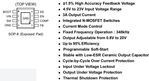
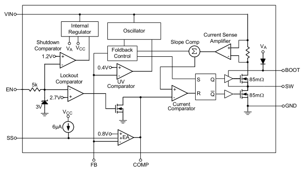
I found the Richtek RT8293A on special for 40c which is step-down converter, 4.5V to 23V input, 0.8V to 20V output, 340KHz operation and up to 3 amp output. There is a heatpad on the bottom of the SO-8 package for better heat dissipation.
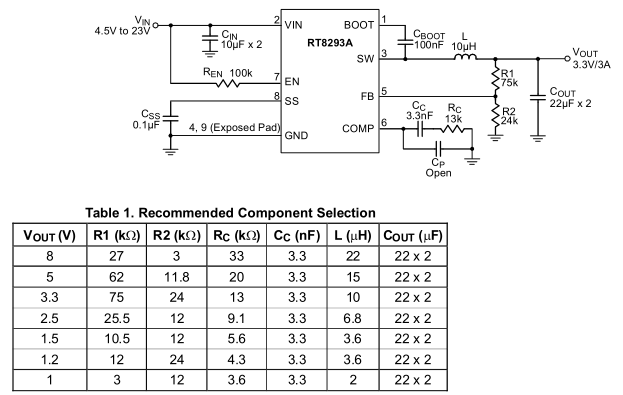
We adjust the output voltage by the resistor divider like before and since we are at a higher frequency we can use a small inductor though there are a few extra components to the RT8293A circuit too but they only add a few cents more to the cost. There is the 3.3nF and 13K for the error amplifier compensation, a soft start feature which uses a 0.1uF capacitor to slowly increase the output voltage, another 0.1uF capacitor to bootstrap the high side driver, a 100K for the chip enable and they recommend 2x 10uF input and 2x 22uF output ceramic capacitors.
PCB Test
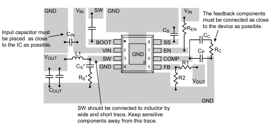
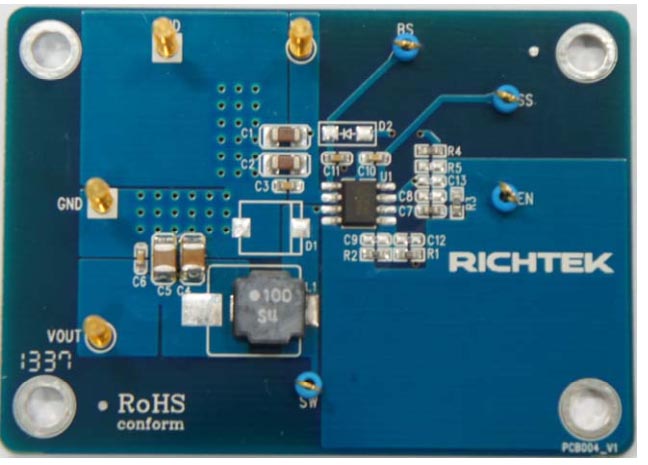
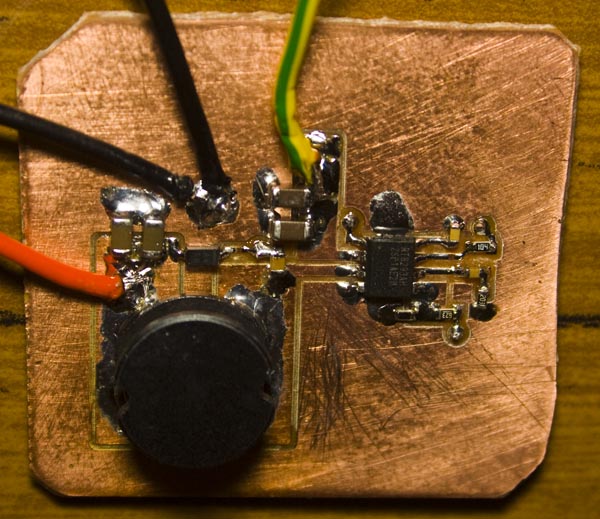
So I went ahead and bought everything that the datasheet said and started designing the PCB around the layout that they provided but looking around there is a reference board made more recently and the layout made a bit more sense so went with that.

The inductor that I used was on special and is a 18uF 7A unshielded one which I’m thinking about re-using for another Richtek chip I bought that delivers up to 6 amps but I should have gone for the shielded option for better EMI. I designed the DC-DC for 5V output, tested it and it worked the first time!
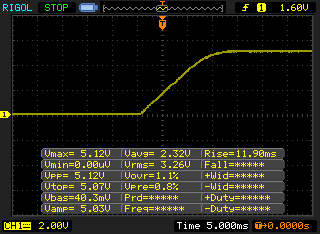
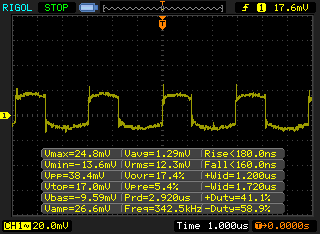
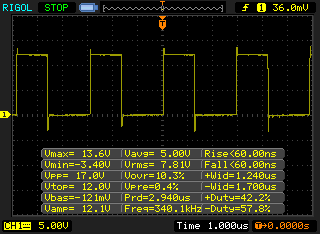
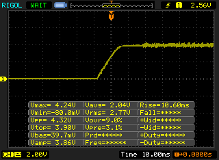
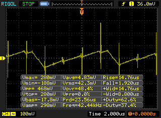
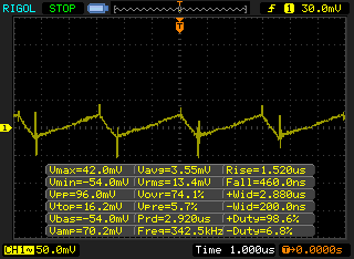
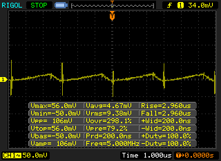
Tested on the scope with no load, we’ve got the ramp up output voltage which looks good, AC coupling of the output (with probe ground lead, so it would be better than this) and the switching frequency before the inductor to confirm it’s 340 KHz. I quickly tested loads on the board – 1 amp made the chip rise to 45C but this could be better if we added more ground near the top of the chip.
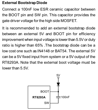
I re-did the PCB to add more ground for heat dissipation and this time added in the optional diode for the bootstrap. Boot strapping allows you to raise the gate voltage on a high side N mosfet by approximately the voltage before the diode which would allow the mosfet to turn on fully (depending on the mosfet), I wish I had know about bootstrapping N mosfets a while ago as I could have used this instead of a voltage doubler.
On further analysis of “Va” the bootstrap voltage, I measured it after the diode and found it to be 3V @ 4.5V input, 4.3V @ 7V input, 4.4V @ 10-12V input so adding our diode should provide a tiny bit more efficiency. I originally went with a regular diode but a schottky diode would be a little better. Upon re-testing the more GND PCB, I’m seeing 40C at 1 amp, 50C at 1.5 amps and 71C at 2 amps.
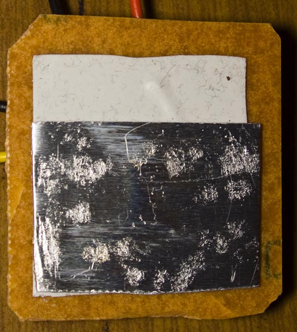
Since this is a single sided board, I added a thermal pad and a piece of aluminum to simulate a ground plane and now see 63C at 2 amps.
Breadboard test
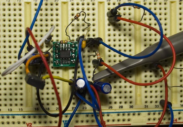
So it works on a PCB but will it work on a breadboard? I always hear about how SMPS’s shouldn’t be done on the breadboard but lets see how each component will affect the output voltage.
Firstly we’ll just add the basic components – 100uF electrolytic caps instead of ceramics, 0.1uF caps for bootstrap/soft start, 100K enable, a 33uH inductor and resistor dividers to give 4V output from a 5V input, it starts up ok but later on you can see the oscillation, the AC waveform is quite bad.

Let’s add a 0.1uF compensation capacitor, it makes it much better than before. There are 3 different types of compensation – type I, II, III and it’s about keeping the error amp stable over frequency (some PDFs on the subject: slyp090 slva662). I changed to the compensation cap to a 2.2nF with 10K in series and there wasn’t too much change.
I added another 100uF cap to the output and the waveform is a bit better. I tried adjusting the output voltage to 3.3V and the waveform is a better but with load these waveforms become worst. Lastly I tried a 100uH inductor but that just increased the voltage spikes. So overall it does work on the breadboard.
Compare against a Ebay $1 DC-DC
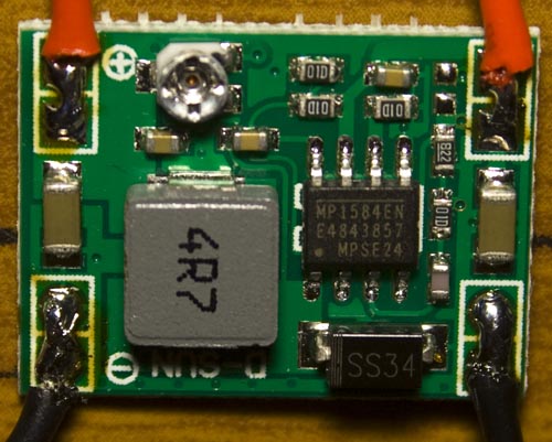
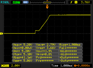
I have a 3 amp DC-DC converter that I bought from Ebay for $1, let’s compare how the RT8293A does against it. Since they are switching at 1.2MHz, they can use a small inductor. The start up ramp to 5V looks good.
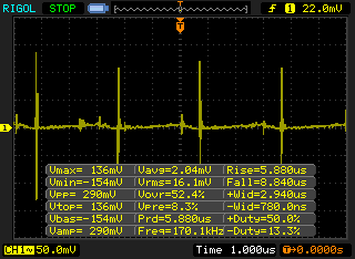
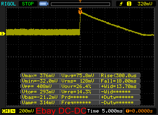
Whilst I was connecting the wires together by accident I noticed there was a spike happening on the output if you connected the 12V input wire and disconnected it 2-3 times a second with no load. With a 700mA load it still happens but only for a brief amount of time – still I wouldn’t want that, the output voltage was 5V.
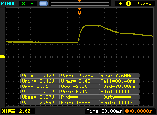
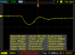
I performed the same test to the RT8293A at 5V and it had no problems with overshoot.
 ,
,
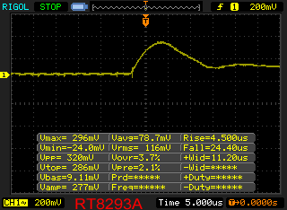
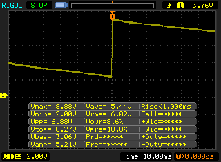
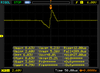
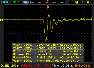
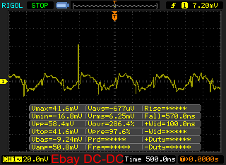
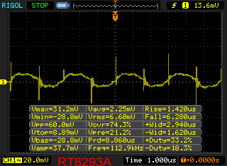
Now lets compare the two side by side, with a 2.5 amp load @ 5V (2x 1 ohm resistors) to test the transient response. When the load is connected, I see a 312mV min on the RT8293A about 112mV more than the datasheet shows but it isn’t as bad as the Ebay DC-DC which shows 600mVmin and then oscillates a bit after that. Once the load is removed, a spike of 296mVmax shows for the RT8293A, it drops down fairly quickly. On the Ebay DC-DC, it’s slighter higher at 376mV but it takes a few milliseconds for it to drop back down to normal.
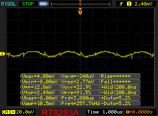
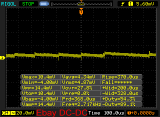
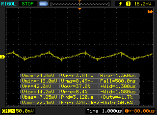
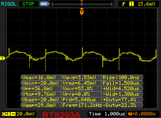
Here we have both with no load. I had to zoom out a bit to capture the oscillations of the Ebay one, I would say they are about the same.


With 1 amp load – RT8293A 40C, Ebay DC-DC 49C.
With 2 amp load. Temps are RT8293A 63C (with simulated ground plane), Ebay DC-DC 67C (@ 1.5 amps), then again the RT8293A PCB (43x40mm) is more larger than the Ebay PCB (22x16mm) so comparing temperatures isn’t really a fair comparison.

With 3 amp load. Both power supplies handled a burst of 4 amps for 1-2 seconds without any issues. I wouldn’t want to leave both of these on at 3 amps as both would get way too hot though if you could use a thermal pad and place it on a piece of metal say on your products case then just maybe that would be enough.
Overall I’m happy with how the RT8293A performs and compared to the Ebay DC-DC it’s better in terms that it doesn’t have the damaging voltage spikes that the Ebay one has, has the same load performance if not a little bit better and is close to the same price. I’ll look at using it for my next SPPS power supply project once I get around to it and for any other power supply needs I might have. I also need to buy some lower inductance shielded inductors and see how they perform so I can reduce the size a bit more.
Part 1: Testing the base circuit configuration
Part 2: Adding an external transistor
Part 3: Revisiting and testing with a constant current load
Part 4: Trying another DC-DC – the Richtek RT8293A, testing PCB/breadboard and load/transient test against an Ebay $1 DC-DC


