Last year, I dismantled my 15 year old RC car and re-built it with an AVR, nRF wireless and N mosfets for the H bridge.
It was all working well until I decided to charge up the Lipo batteries to full which was just enough to voltage to fry (and catch fire) one of my high side mosfets from the voltage doubler (should have used boost strapping instead). Now it’s time for me to re-visit this project – use P & N mosfets, change the wireless to 433MHz for more range and add some controllable front/rear lights.
Originally I was going to use the ATtiny85 but since I want the lights to be controllable I need a few more pins so I’ll be using the ATtiny84. Most of the 433MHz receive/transmit code can be re-used from my Alarm system – Remote control upgrade and most of the rest could remain the same.
DDRB |= (1<<PB2); // Motor forward control
DDRA |= (1<<PA7); // Motor reverse control
TCNT0 = 0;
OCR0A = 0; // Sets motor forward duty cycle to 0%
OCR0B = 0; // Sets motor reverse duty cycle to 0%
TCCR0A |= (1<<COM1A1) | (1<<COM1B1) | (1<<WGM00); // PWM, Phase Correct and OCRA/B outputs
TCCR0B = (1<<CS01); // 8 prescaler
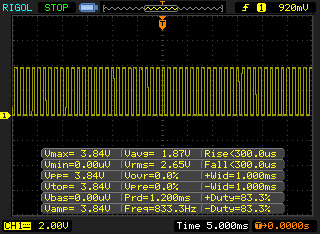
I decided to simplify the PWM to the motors and have it done all in hardware rather than using timers with interrupts like I did before.
So now to turn on the motor in the front direction we set OCR0A and OCR0B for the back direction, I tested to see that when the motor was running and we switched to the other direction that it wouldn’t run both at the same time for a few moments, looks good.
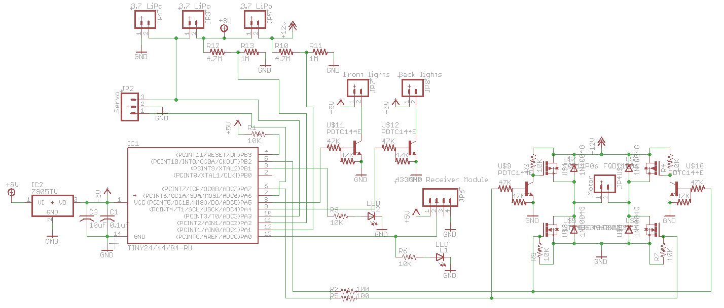
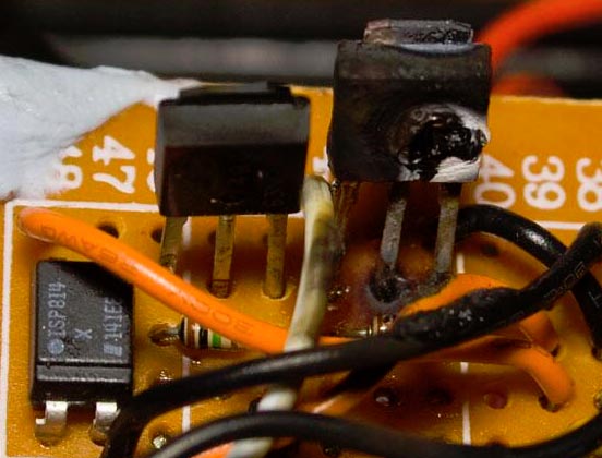
Instead of connecting 3x Lipos all together and using an additional Lipo for the ATtiny like I did last time, this time I’m having an connector on board for each battery so we save 1 battery. We’ve got optional monitoring of cell voltage via the resistor dividers, have PDTC144E NPN transistors with built in resistors for the lights and FQD11P06 P mosfets which we are using the NPN to pull down when we want them to be on.
Also we have a LM7805 for the AVR, 433MHz receiver and I used to have the servo motor connected to it too but switched to run it from the first Lipo now. I found that when moving the servo and then trying the motor just caused it to lock up randomly.
After that another issue occurred, I found that when I connected more than 7.5V to the LM7805 input that I received a strange constant waveform on the 433MHz receiver. I tried adding capacitors, testing the receiver on it’s own, the servo, etc with no luck.
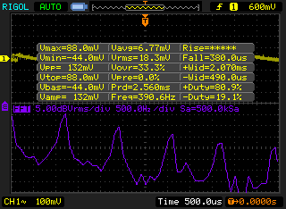
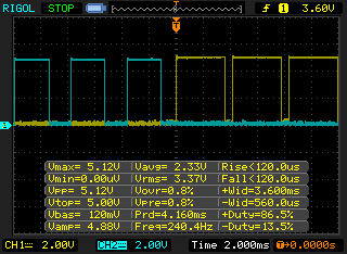
Eventually I moved on to testing the LM7805 and at first with no load it looked fine however upon putting a light load such as a 1.5K resistor we see a huge problem in the FFT view.
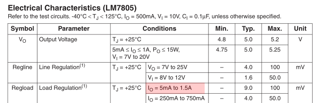
Using a 220 ohm resistor puts enough load on it and fixes it up so I added that to my circuit. In the datasheet, it does show 5mA to 1.5A load regulation, something that I didn’t realise (some datasheets I believe do have a text that says “minimum load” or similar).
In regards to the 433Mhz transmission – at first I started with sending a preamble of “10101101” and checksum at the end when I was transmitting the 3 bytes – motor control, servo control and lights repeatedly but found there was an issue where some of the data I was transmitting wasn’t being received correctly.
// 6 bit CRC calculation
uint8_t crc6Bit = 0;
for (uint8_t x = 0; x < 3; x++) {
	crc6Bit += data_out[x];
}

// Only care about low 6 bits
crc6Bit = crc6Bit & 0x3F;
data_out[LIGHTS_AND_CRC_CHECK] |= crc6Bit;
I went with using the last 6 bits of the third byte for a CRC of the all the bytes which should give a better result than the 1 bit checksum we used before (but we still continue to use it too) and now it all works good again.
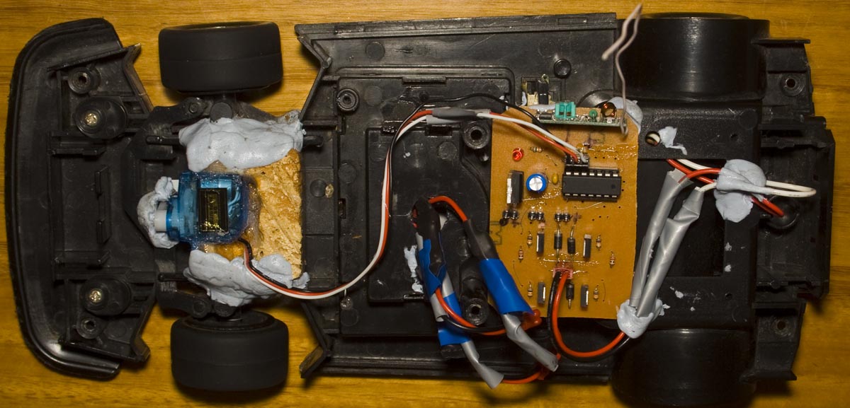
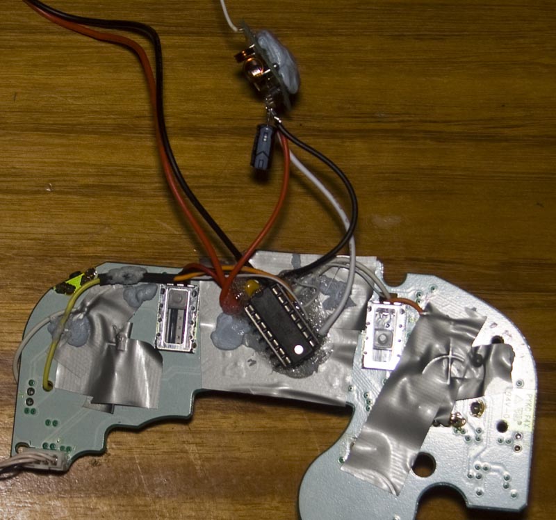
Here’s how it all looks, I did a PCB for the RX side, have fuses on each of the Lipos and we’ve got the Gamecube controller once again as the remote – the front/back lights are on the L and R buttons, hold them down for a few seconds and they stay on. Download 433MHz_RC_Car_v0.1


