A few months ago I bought myself a really cheap camera so I could record the front of my car whilst driving (dash cam), it cost $6 off Ebay. I’ve seen lots of dash cam videos and thought I’d join in too as there have been those kind of moments where you just wish you had a camera. Instead of manually turning the camera on, off and then pressing record I wanted to automate this with an MCU.
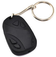
The camera has two buttons – one to switch it on and off and the other button to record or take a picture. It has a microSD card slot and USB connector which you can use to grab your pictures/videos and charge the built in Li-Poly battery.
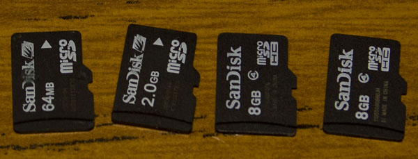
One other thing to mention is that I’ve found if the battery goes flat when you are recording it destroys the microSD card – you can still read from it but can’t write to it any more – maybe I just have a bad batch? Above are all the microSD cards which suffered this fate. A downside with this camera is that it records everything in MJPEG which means your microSD card will be used quickly – a 27 minute recording was 2.4GB but what can you expect for the cheap price.
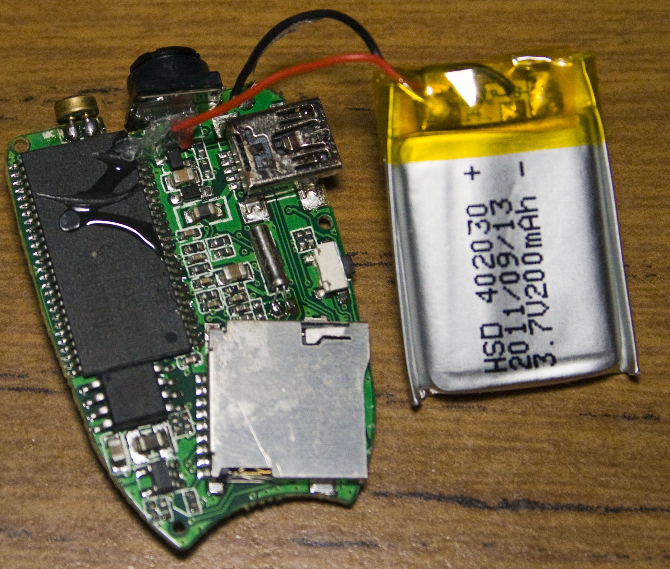
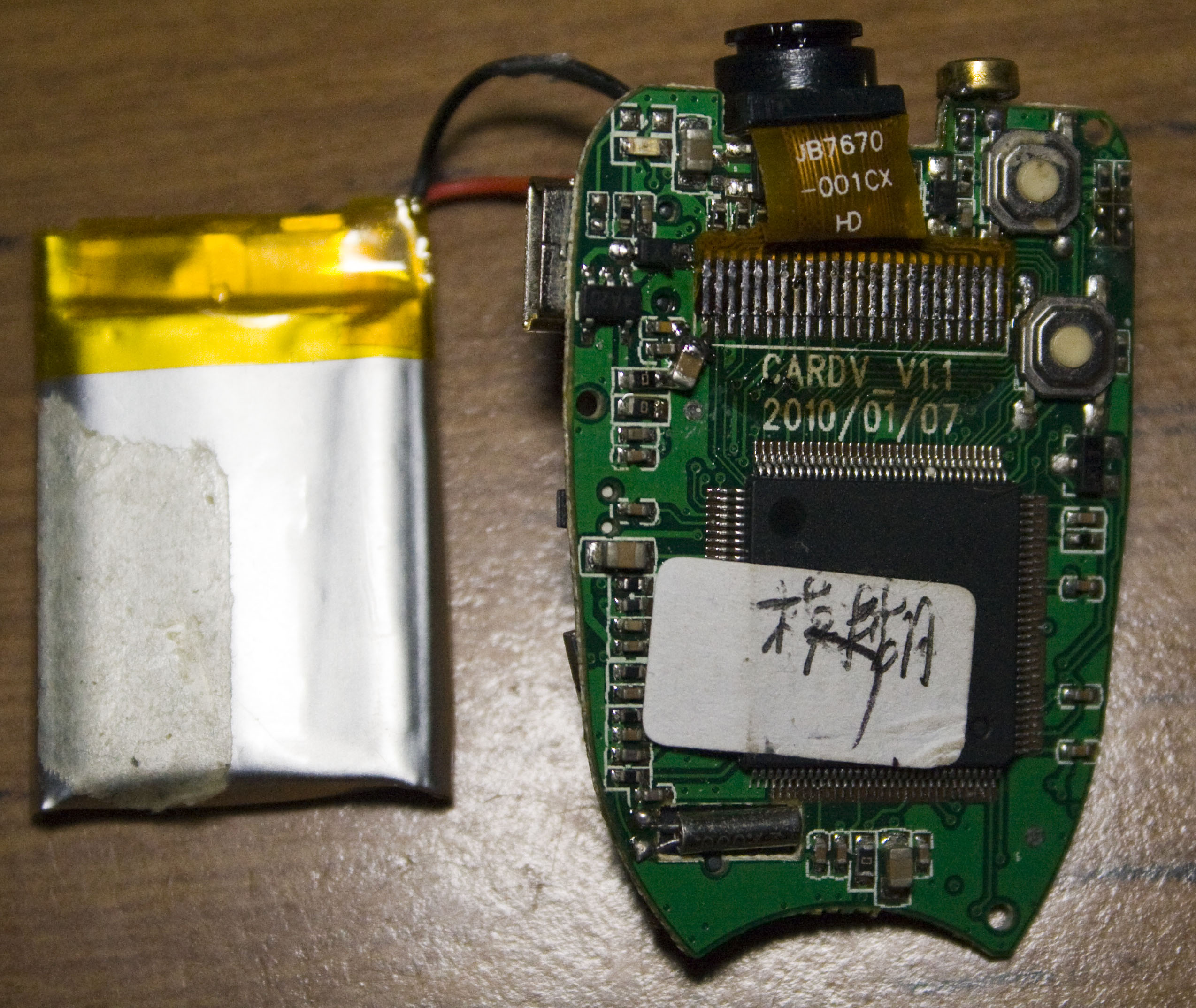
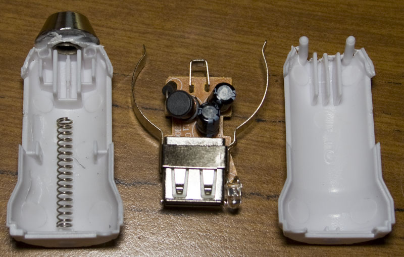
Two screws later and we’re in. We can see the Li-Poly capacity is 200mAh, we have a memory chip to the left and the processor chip to the right. I found that when the camera was turned on or recording, it draws 105-120mA and when the Li-Poly battery is charging the charger supplies it with about 100mA and slowly starts dropping current.
My first thought was to check if it could be powered by the USB and also be recording at the same time but that didn’t work. Another possibility is to remove the battery and connect another 3.7 – 4.2V source to where the battery was which works fine, but if we are powering the camera from the car as soon as the car turns off, the power to the camera would stop and corrupt/destroy our microSD card. I experimented with capacitors – lots of them but there just wasn’t enough capacitance to keep it on for a 100-200 milliseconds to stop the recording. I also tried using lots of capacitors and then switching in the Li-Poly as a backup battery using a mosfet but it was all more complicated than it needed to be.
Li-ion/Poly charger
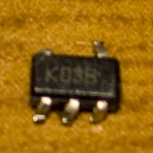
It was time to look into using a Li-ion/Poly charger so I could potentially leave the battery as is and have the charger supplying power when the car was on and then have the battery acting as a UPS which would take over when the car was switched off and then the MCU would switch the camera off. I chose the MCP73831 – a small SOT23 device for charging a single cell Li-ion/Poly battery, charge voltage can range from 4.2 – 4.5V (depends on the chip you buy) and a programmable current of 15mA – 500mA. This charger seems to be used almost everywhere and the price was only $1. There is a good video from EEVBlog on a Li-ion/Poly charging tutorial which explains the 3 modes of charging that these chargers do. With Li-ion/Poly batteries you need to be very careful to charge the battery to the correct voltage.
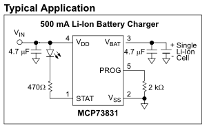
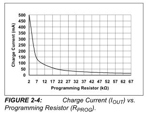
The MCP73831 is very simple to use – all you need to do is select a resistor to use for the program (PROG) pin. A 10K resistor would give us about 100mA which suits us perfectly. You can also have an LED connected to the STAT pin which will stay on whilst the battery is being charged and turn off once the charging is complete.
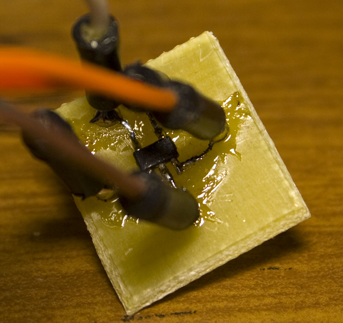
I made a small PCB to mount the MCP73831.
Car charger power
I had an existing car charger for a mobile phone which I tested the camera directly from it however I found that the voltage dropped from the rated 5V to about 4V or less with only a draw of 100mA, this won’t suit us at all.
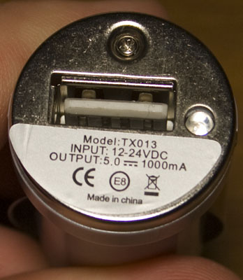
I decided to buy a cheap car charger which claimed 5V at 1A but mostly I bought it because it had screws which means if it didn’t deliver the rated voltage/current I should be able to easily take it apart and use an LM7805.
It also had the same issue as the other one so I took it apart and I will be able to fit the LM7805 in there.
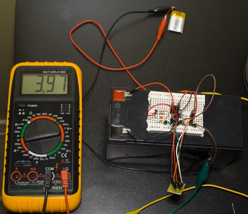
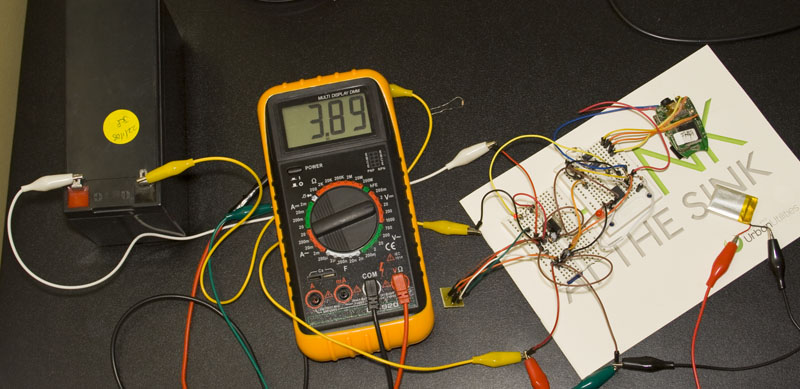
Now I can test the LM7805 with the MCP73831 to charge the Li-Poly battery. After leaving it for an hour or two, the battery was charged.
Schematic / Code
We can move on to the schematic / code, I’ll be using an ATtiny25.
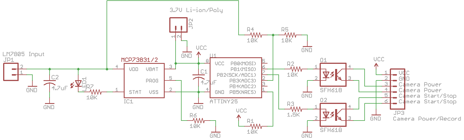
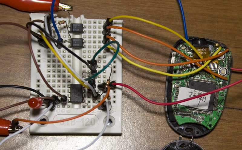
From the schematic you can see the Li-ion/Poly charger and see that we are using optocouplers to switch the buttons on and off, I found that the camera recording button needed a smaller value resistor so there would be less resistance on the output side because I found using a 10K resistor had no effect on it. Also you’ll notice the 10K resistor divider which connects to the input of the charger, this will let us know when the car is started.
The code is basic as we are just switching outputs on and off.
#define powerPin PB1
#define recordPin PB2
#define sensePin PB0
...

// Sleep until the Watchdog timer wakes us up
watchdogSleep(T4S);

// Read sense pin, if read high then start the camera, otherwise turn off camera if it was previously on
if (PINB & (1<<sensePin)) {
  if (cameraOn == false) {
    // Turn on camera
    PORTB |= (1<<powerPin);
    _delay_ms(2000);
    PORTB &= ~(1<<powerPin);
    _delay_ms(1000);

    // Start recording
    PORTB |= (1<<recordPin);
   _delay_ms(10000);
    PORTB &= ~(1<<recordPin);

    cameraOn = true;
  }
}
else if (cameraOn == true) {
  // Stop recording
  PORTB |= (1<<recordPin);
  _delay_ms(200);
  PORTB &= ~(1<<recordPin);
  _delay_ms(1000);

  // Turn off camera
  PORTB |= (1<<powerPin);
  _delay_ms(5000);
  PORTB &= ~(1<<powerPin);

  cameraOn = false;
}
I thought about using the pin change interrupt but I don’t know how much the car charger/LM7805 would fluctuate when the car is started so I went with the watchdog timer of 4 seconds with a variable to know whether the camera is on or off. The MCU will always running from the Li-ion/Poly but since it’s sleeping 99% of the time it will only draw ~5uA from the battery. We just hold the power button down for 2 seconds and then hold down the recording button down for 10 seconds. When powering off, we press the record button and then hold down the power button down for 5 seconds to switch it off. Download ATtiny25_CPRC.
After testing for a few minutes it all seems to work well, one thing I have found is that since the camera can draw 120mA, I should decrease the program resistor to 7-8K otherwise it will draw the rest of the current (~20mA) from the battery.
Edit: If you are looking for a camera that automatically records and aren’t looking to do what I’ve done, you can buy one from Ebay for about $25.


