Welcome back to Part 4, we now get to see some results of our work :). The video below shows the ATtiny85 running at 5 volts with our standalone temperature logger software and retrieving the data from the ATtiny’s EEPROM and printing it on our computer screen.
Why did I mention “ATtiny85 running at 5 volts”? It’s because we aren’t quite done yet with this project, the next step which is Part 5 is to adjust our code and schematic to run the ATtiny85 on 2 AA batteries. Then after that we need to make a PCB of it!
Download the Temperature_Logger_ATtiny_v1 for ATtiny85 and the Temperature_Logger_Arduino_Reader_v1 for Arduino.
There hasn’t been much changed in our code, we’ve just re-assigned the pins.
int ledPin = 0;
int thermistorPin = 1; // Analog input 1
int buttonPin = 4;
int dataPin = 1;
int clockPin = 3;
The Analog input actually caught me out, it’s important to know for the ATtiny85 Arduino implementation that we used, when doing anything with Analog pins we look at the “Ain1” part of the diagram below and not the “D 2” part.
                  +-\/-+
Ain0 (D 5) PB5  1|    |8  Vcc
Ain3 (D 3) PB3  2|    |7  PB2 (D 2)  Ain1
Ain2 (D 4) PB4  3|    |6  PB1 (D 1) pwm1
           GND  4|    |5  PB0 (D 0) pwm0
                 +----+
What I did by mistake was assign thermistorPin as pin 2 instead of as pin 1 like it should have been, that gave me strange results until I figured it out. The “D 2” stands for Digital pin 2! Plus you wouldn’t know anything about using “Ain1” as pin 1 unless you actually looked in the pins_arduino.c file deep in the zip file, so take note of this!
Time to jump into my simple 2 wire protocol, as in Part 1 one wire is the clock (CLK) and the other is the data. You might also remember I was hoping to get the clock high in 1 ms, read the data bit in that 1ms and then 1ms of clock low. To actually do that we would need an interrupt on the ATtiny and I thought that I’d like to keep things simple so I didn’t use interrupts. We still retain our data rate of 62 bytes a second.
I made the Arduino send a HIGH clock for 1 ms, the ATtiny detects this high and waits. Now the Arduino sends a LOW clock for 1 ms, one the ATtiny detects the clock is no longer HIGH it outputs 1 bit of data. After the Arduino is done waiting 1ms with the LOW clock it reads the data bit and then outputs HIGH and the loop starts again.
Let’s check how we begin the simple 2 wire protocol from the Arduino side.
Arduino initialising my simple 2 wire protocol side
int clockPin = 2;
int dataPin = 3;

boolean inTransfer = true;

void setup() {
 pinMode(clockPin, OUTPUT);
 pinMode(dataPin, INPUT);
 pinMode(13, OUTPUT);
 Serial.begin(9600);
}
Just standard pin assignments here plus a intransfer variable and we start our serial connection to the computer.
void loop() {
 digitalWrite(clockPin, LOW);
 delay(50);
 digitalWrite(clockPin, HIGH);
 Serial.println("Ready");
Now we start the main code, we set clockpin to low and wait a bit just to be sure nothing weird is going on. To start my protocol we need some kind of way to say to the ATtiny that we want it to be initialised for us to read it’s EEPROM, to do this I thought why not send a clock of high then wait for a data high from the ATtiny for 250ms to confirm it’s received the request? We set clock as high and tell our computer we are ready.
  boolean dataReady = false;
 int datainCount = 0;
 while (dataReady == false) {
   delay(25);
   int dataIn = digitalRead(dataPin);
   if (dataIn == HIGH) {
     datainCount++;
   }
   else {
     datainCount = 0;
   }
   if (datainCount >= 9) { // At least 225ms high, get ready
     dataReady = true;
     digitalWrite(13, HIGH);
     while (dataIn == HIGH) { // Wait for data low
       dataIn = digitalRead(dataPin);
     }
   }
 }
Now we were going to check for a high from the data wire. We have a loop, we delay 25ms, check the data line to make sure it’s still high and then increment the dataincount variable. This is to make sure that the ATtiny isn’t suck in some kind of loop that it’s sending us highs and lows. Once dataincount equals 9 (225ms), we turn on the Arduino’s LED indicating it’s now ready and we keep reading the data line until it goes low. It will go low, because the ATtiny knows to only send a data HIGH for 250ms.
To make it easier to see, above is the visualisation of it and what the ATtiny will do which we will explain below.
ATtiny initialising my simple 2 wire protocol side
Let’s jump to the ATtiny’s initialisation, the code below is running when we turn on the ATtiny.
int clockState = digitalRead(clockPin);
 if (clockState == HIGH) {
   int clockhighCount = 0;
   // Delay for 10 x 25ms = 250ms, check CLK is always high
   for (int x = 0; x < 10; x++) {      delay(25);      clockState = digitalRead(clockPin);      if (clockState == HIGH) {        clockhighCount++;      }      else {        clockhighCount = 0;      }    }    // CLK is high, now give the 250ms HIGH as an ok    if (clockhighCount >= 10) {
     functionSelect = 3;
     digitalWrite(dataPin, HIGH);
     delay(250);
     digitalWrite(dataPin, LOW);
   }
 }
First we begin by reading the clock pin, is it high? If so, we count for how long it’s high for which is kind of what we did for the Arduino initialisation above. We delay 25ms for 10 times and if the clock has always been high we then turn the data line to high for 250ms (which is what the Arduino reads) and set functionselect to 3. Now both the Arduino and ATtiny are initialised.
Arduino sending clock
Now we are to the point where the Arduino can pulse the clock high and low for 1ms each.
while (inTransfer == true) {
 byte dataByte = 0;
 for (int x = 7; x >= 0; x--) {
   digitalWrite(clockPin, HIGH);
   delay(1);
   digitalWrite(clockPin, LOW);
   delay(1);
   int dataIn = digitalRead(dataPin);
   if (dataIn == HIGH) {
     bitWrite(dataByte, x, HIGH); // Write the bit received to dataByte
   }
   Serial.print(dataIn, DEC);
   }
   if (dataByte == 0) { // Received 00000000, we are done reading
     inTransfer = false;
   }
   else {
     Serial.print(" = ");
     Serial.print((dataByte-130), DEC); // Convert to real temp
     Serial.println();
   }
 }
 digitalWrite(clockPin, LOW);
 digitalWrite(13, LOW);
 while (1);
}
While we are in still our transfer we assign databyte as our variable that will store all 8 bits received from the ATtiny. We begin our loop that happens 8 times that makes up our 8 bits. Clock goes high for 1ms, then low for 1ms and then we reach the data line. If it’s high, we write to our databyte the specific bit that was high, we transfer most significant bit first (most left bit). We also print this bit out on the serial line.
Now how can we get the Arduino to stop sending clocks once the ATtiny has send us all the data? We can do it by just having the ATtiny send us nothing back for 8 clock cycles which means we get a databyte value of 0. If we do, we stop the transfer and turn off the clock and LED (seen at the bottom of the code). If all the databyte wasn’t 0, we print out the databyte as a decimal minus 130 from it to get our true temperature value (if you remember in Part 2 we added 130 to the temperature value).
ATtiny receiving clock
if (functionSelect == 3) {
   digitalWrite(ledPin, HIGH);
   boolean inTransfer = true;
   int readCount = 1;
   while (inTransfer == true) {
     byte dataByte = 0;
     if (readCount < 512) {        dataByte = EEPROM.read(readCount);      }      for (int x = 7; x >= 0; x--) {
       digitalWrite(dataPin, LOW);

       // Wait until CLK is low
       long resetTimer = millis();
       int clockIn = digitalRead(clockPin);
       while (clockIn == HIGH && inTransfer == true) {
         clockIn = digitalRead(clockPin);
         if (millis() > resetTimer + 250) {  // Check if host is restarting the CLK
           inTransfer = false;
           functionSelect = 0;
         }
       }

       // Output the bit
       boolean dataBit = bitRead(dataByte, x);
       digitalWrite(dataPin, dataBit);

       // Wait until CLK is high
       resetTimer = millis();
       clockIn = digitalRead(clockPin);
       while (clockIn == LOW && inTransfer == true) {
         clockIn = digitalRead(clockPin);
         if (millis() > resetTimer + 100) {
           digitalWrite(dataPin, LOW); // Don't want to wait 250ms for this otherwise Arduino will think it's beginning from the start again
         }
         if (millis() > resetTimer + 250) { // Check if host is restarting the CLK
           inTransfer = false;
           functionSelect = 0;
         }
       }
     }
     if (dataByte == 0) { // No more data to send
       inTransfer = false;
       functionSelect = 0;
     }
     readCount++;
   }
 }
For the ATtiny we turn the LED on once it’s in our EEPROM reading function. As we did for the Arduino we have similar variables but this time have a readCount variable to track the EEPROM address. If the EEPROM address is less than 512 we read from the EEPROM. We go into the for loop, it runs for 8 times and during each time. We firstly make sure the data line is low, then take note of the milliseconds since the ATtiny booted up as it’s important for later use.
Take note that ATtiny we have doesn’t have a external crystal so if we wanted to time things perfectly it’s a good idea not to use any time related features on it, like delay(1) for this part, instead how about we let the Arduino be our timing mechanism? So I did, I keep the ATtiny stuck in a while loop always reading the pin. We read the clock and expect it to be high and wait in the while loop until it goes to low. Now if we have waited for 250ms, something is wrong so we terminate the transfer and go back to the main loop of our program.
If we do see the clock change to low, we read the individual bit of the databyte variable and send that through the data line. Now we have another waiting while loop, we wait until clock changes from low to high. Our timing terminate check is also in this while loop too except we have it change the data line to low after 100, why? It’s because if we wait for 250ms and something has happened to the Arduino, like it reset, it might think the ATtiny is sending the initialisation complete which isn’t true. Now in the occurrence that we reached the 512 EEPROM address, databyte stays as 0. After we send 0 in the data line for 8 times, it checks if databyte is 0 which it is and then we terminate back to the main loop.
And that’s my simple 2 wire implementation complete and it does work! :).
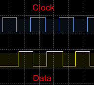
Now to see something pretty, above is the transfer between the Arduino and ATtiny with each time the ATtiny sending 10011101 or 157 in dec (157 minus 130 is 27C temp).
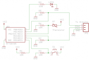
The schematic of the ATtiny85 running at 5 volts is below, this schematic will change once I use 2 AA batteries.
See you next time!


Great project!
One link came up “404” for me: http://www.insidegadgets.com/2011/01/23/wp-content/uploads/2011/01/Temperature_Logger_Arduino_Reader_v1.zip
Is the “Temperature_Logger_Arduino_Reader_v1” .pde available somewhere?
Ah yes I’ve re-checked the link and it should work again. I’ve downloaded a WordPress add-on now to check all links in my posts, thank you for bringing these 404s to my attention.
http://www.insidegadgets.com/wp-content/uploads/2011/01/Temperature_Logger_Arduino_Reader_v1.zip