Posted in Projects on Nov 5th, 2011
Today we’ll be making a modification to the Standalone Temperature Logger which will allow us to log voltage instead of temperature. I would like to log the voltage of a 12 volt battery or the small solar panel that’s charging it, so I’m aiming for a voltage range of 0 to 15 volts.
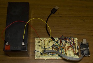
The ATtiny85 in the SATL is powered by a 3 volt battery and the ADC (analog to digital converter) measures 0 – Vcc by default (3V in this case). How can we use the ADC (analog to digital converter) to increase its range to 15V? We can use a voltage divider to divide the voltage by a certain ratio.
Read Full Post »
Posted in Projects on Oct 31st, 2011
So I was making a modification to the Standalone Temperature Logger (SATL) to make it log voltage instead of temperature and happen to discover an issue with the Brown-out Detector which is set to 2.7V. Download the SATL v2.1 or visit the SATL project page.
It turns out that I had a 3V coin cell which was a bit discharged as it was sitting at 2.95 volts and when I connected it to the circuit it would drop to 2.7 volts and draw about 0.5mA of current which was very odd. At 2.95 volts I thought it should still have some life left. After trying to program very simple programs to the ATtiny85 like a blinking LED, making it sleep right away, etc I had no success. Eventually I reset the fuse bits and it all started working well again which lead me to discovering that BOD was the issue.
I tried adding 0.1uF, 4.7uF and 470uF capacitors which sometimes worked but it wasn’t reliable. I’m now recommending that BOD be disabled for the SATL unless you know the 3V coin cell is brand new or near new condition. The BOD issue brought my attention to other places within the SATL that could be improved upon.
Increase the button pull down resistor
Connected to the button we have a standard 10k pull down resistor and each time the button is pressed or held 0.3mA is consumed, seems sort of wasteful.
(more…)
Read Full Post »
Posted in Projects on Jul 10th, 2011
The Standalone Temperature Logger has now been updated to v2.0 with the PCB, schematic, guide and source all available for download.
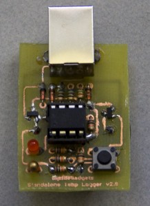
I kind of took a little break and came back to figure out the PCB, once it was done all that was left was to try it out and create the new documentation for it. Since I’m using 2 SMD Mosfets I thought that soldering them would be really difficult but it turned out to be easier than I expected. Testing went well and am quite happy with how it turned out.
So go ahead and check out the updated project page for the Standalone Temperature Logger v2.0.
Read Full Post »
Posted in Projects on Jun 18th, 2011
Last week we built an automatic voltage switching circuit and now it’s time to apply this circuit to the Standalone Temperature Logger (SATL).
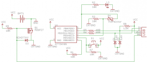
Let’s bring up the new schematic for the SATL with the voltage switching circuit. As you can see like last week, we separate the grounds of the voltage sources – the 3V battery and USB. Notice that CRTGND is not the same as GND, CRTGND connects to the mostfet drain/schottky diode.
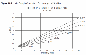
There is a downside to this circuit which is that there is a voltage drop when running from the USB side due to the diode. The USB voltage can vary between 4.75V to 5.25V and the good news is that our ATtiny85 can run fine at 16.5MHz whilst at 4.0V.
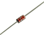
If the USB voltage was really 4.75V, we would just make it to 4.05V but we want the best possible voltage even if it was 4.75V. Instead of using just a standard diode we’ll use a schottky diode which can provide a lower voltage drop of 0.3V instead of the 0.7V from standard diodes.
(more…)
Read Full Post »
Posted in Projects on May 29th, 2011
Today I’ll be showing how we can integrate the Standalone Temperature Logger (SATL) into the V-USB Test program we have. It’s taken me a little while to find my way around V-USB and its kinks.
Schematic
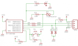
The schematic has been updated to include the USB port. Another change is that when the LED turns on it also turns on the thermistor, before we used to do this with the dataPin.
Cleaning up the V-USB code
The first thing I’ve done is copy over our setup.c file from the SATL WinAVR to our project and then move everything related to V-USB setup or procedures (except the sending of keys) to our setup.c file which now leaves us with just two functions in main.c (evaluateADC and main).
Next I would like to cut down on the main’s USB setup code, lets make a new function called startUSB() and place all the code below in it.
(more…)
Read Full Post »
Posted in Projects on May 14th, 2011
Today we’ll be modifying the ATtiny85_Blink WinAVR example to convert the Standalone Temperature Logger from using the Arduino software to WinAVR so that we can easily integrate it in with V-USB. Download here: Standalone_Temperature_Logger_v2.0_Beta_1
Changes to setup.c
Let’s begin with the setup.c file, to make things easier we will put all of our commonly used functions in this file too.
// Used from http://www.arduino.cc/playground/ComponentLib/Thermistor2
double Thermistor(int RawADC) {
  double Temp;
  Temp = log(((10240000/RawADC) - 10000));
  Temp = 1 / (0.001129148 + (0.000234125 * Temp) + (0.0000000876741 * Temp * Temp * Temp));
  Temp = Temp - 273.15; // Convert Kelvin to Celcius
  return Temp;
}
First we put in the Thermistor function without any changes made.
// Used from http://interface.khm.de/index.php/lab/experiments/sleep_watchdog_battery/
void system_sleep(void) {
  DDRB &= ~((1<<ledPin) | (1<<dataPin)); // Set outputs to inputs to save some power
  cbi(ADCSRA,ADEN); // Switch Analog to Digital converter OFF
  set_sleep_mode(SLEEP_MODE_PWR_DOWN); // Set sleep mode
  sleep_mode(); // System sleeps here
  sbi(ADCSRA,ADEN);  // Switch Analog to Digital converter ON
  DDRB |= ((1<<ledPin) | (1<<dataPin)); // Set those outputs back to outputs
}
Next we insert the system_sleep function, other than the switching between outputs and inputs which is done using DDRB. Notice that we have referenced ledPin and dataPin, we will define those ports in the main.c file.
(more…)
Read Full Post »
Posted in Projects on Mar 15th, 2011
Just a quick post to let you all know that the Standalone Temperature Logger has now been updated to v1.1. This update is for the re-design of the PCB board, it’s now been adjusted so that there are components close to the battery solder joints thus making it easier to solder the battery.
Visit the Standalone Temperature Logger project page to view/download the update.
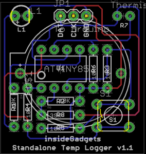
Read Full Post »
Posted in Projects on Mar 5th, 2011
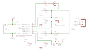
Welcome to Part 9, we have our schematic from Part 7 as below now it’s just time to design and build our PCB. Not a whole lot of content for this post, mostly just pictures.
First thing I did was position the ATtiny85 near the center of the board and position the resistors as close to each other as possible. After that it was just a matter of finding where everything else fit. To make the board as small as possible I decided that I would mount the battery on the back of the board.
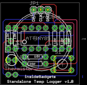
(more…)
Read Full Post »
Posted in Projects on Feb 20th, 2011
Welcome to Part 8, before we get starting with making the PCB I thought I’d review my code/hardware plus add some more functionality to our project.
We don’t need a Watchdog f_wdt variable
On review of my code and the example watchdog code I used, I found that the watchdog f_wdt variable wasn’t adding any value to our code. I came to this conclusion because when you run the system_sleep() function and it reaches sleep_mode(); it sleeps there. When the Watchdog timer wakes it up, it heads to the watchdog vector (ISR(WDT_vect)) and now since it’s awake again it continues to run next bit of code.
// This will work because we are initialising the watchdog vector and
// once the watchdog times out, it will wake up, go here,
// do nothing and continue our code
ISR(WDT_vect) {
}
Now I’ve give you an example of where we might need the f_wdt variable.
(more…)
Read Full Post »
Posted in Projects on Feb 13th, 2011
Welcome back! In this part we’ll explore how we can reduce our power consumption which will allow us to move from 2 AA batteries to a 3V coin cell.
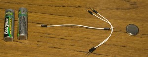
When the whole circuit is operating in logging data mode and at 2.68 volts, it’s taking up 1.06mA. First off this 1mA is much lower than our assumed 2-3mA because we are running at 3V instead of 5V, less voltage means less power consumption. Using the Battery Life Calculator with a 240mAh battery it gives us a estimated battery life of 8 days. Lets see how low we can get our power consumption to!
(more…)
Read Full Post »


