Welcome to Part 8, before we get starting with making the PCB I thought I’d review my code/hardware plus add some more functionality to our project.
We don’t need a Watchdog f_wdt variable
On review of my code and the example watchdog code I used, I found that the watchdog f_wdt variable wasn’t adding any value to our code. I came to this conclusion because when you run the system_sleep() function and it reaches sleep_mode(); it sleeps there. When the Watchdog timer wakes it up, it heads to the watchdog vector (ISR(WDT_vect)) and now since it’s awake again it continues to run next bit of code.
// This will work because we are initialising the watchdog vector and
// once the watchdog times out, it will wake up, go here,
// do nothing and continue our code
ISR(WDT_vect) {
}
Now I’ve give you an example of where we might need the f_wdt variable.
...
 system_sleep();
 if (f_wdt == 1) { // The Watchdog woke us up
 }
 if (f_pin == 1) { // The pin change woke us up
 }
...

ISR(WDT_vect) { // Watchdog
 f_wdt=1;
}

ISR(PCINT0_vect) { // Pin change
 f_pin = 1;
}
Say we actually have 2 interrupts, the watchdog and pin change; a pin change is when the microcontroller monitors a pin to see if it changes state, we want to know when either happens. When the microcontroller wakes up from it’s sleep if we don’t use the f_wdt variable and change it’s value to say 1, we won’t know which interrupt actually woke it up.
...
 system_sleep();
 if (f_pin == 1) { // The pin change woke us up
 }
 else { // It had to be the Watchdog that woke us
 }
...

ISR(WDT_vect) { // Watchdog (remember this is still needed!)
}

ISR(PCINT0_vect) { // Pin change
 f_pin = 1;
}
A way around this might be to just use 1 interrupt vector for the pin change and say if it wasn’t the pin change that woke it up then it had to be the watchdog.
*** Delete these lines from our code ***
volatile boolean f_wdt = 1; // Watchdog variable
f_wdt = 1;
if (f_wdt == 1) {
 f_wdt = 0;
} (the ending bracket to the if statement)
f_wdt = 1; // Set global flag
So lets remove the f_wdt variable from our code as it’s not needed.
We can remove the sleep_enable/disable functions in sleep_mode
After some investigation, it appears that we don’t need the sleep_enable or sleep_disable functions because the sleep_mode function does this for us. I was looking into the AVR-libc sleep.h documentation file which showed an example as below.
#include <avr/sleep.h>
 ...
 set_sleep_mode(<mode>);
 sleep_mode();
Upon looking directly into the avr/sleep.h file I found the sleep_mode() function which does indeed call sleep_enable/disable for us already as shown below.
#define sleep_mode()
do {
 sleep_enable();
 sleep_cpu();
 sleep_disable();
} while (0)
#endif
So that’s a doubling up we can remove, I guess it’s a good idea to review the AVR-libc documentation every now and then!
Why are there no capacitors
Normally you would see a 100uf and 0.1uf on the VCC / GND line but as we our circuit doesn’t have high current demands / bursts of high current and because we want to make things as low cost as possible we won’t use any capacitors.
Enable pin change interrupt for button to Arduino
Previously in order to stop the temperature data logging so we could choose another function like communicating to the Arduino we would have to remove and re-insert the battery/power to set it back to the “listening mode” where it listens for which function to run. What we’ll do now is to set-up a pin change interrupt that we can actually have monitoring for any changes from the button. This also allows us to save power consumption when our device is idling, i.e waiting for the user to press a button to start.
We’ve learnt about the watchdog interrupt before, so pin change interrupt is just that, if a pin is pulled to ground (LOW) and then it becomes HIGH we can have it trigger an interrupt. When the interrupt is triggered as like the watchdog does, it also wakes up the microcontroller from sleep.
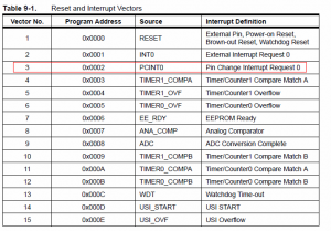
From the ATtiny85 datasheet, we can see that in the power-down mode, we can use the Pin Change as a wake up source. Lets jump to the Interrupts page and find out what the vector name for Pin Change is called.
It appears to be named PCINT0, so we’ll take a note of it. Now we’ll scroll on down to the Register Description and look for a way to enable the Pin Change interrupt.
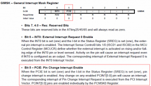
We see a register called GIMSK and the 5th bit appears to handle the Pin Change Interrupt Enable. Be sure to read the description, it mentions that we need to set the PCIE bit in GIMSK to one plus set the I-bit in SREG to one too and then set which pins we are enabling this pin change interrupt on in the PCMSK register. From our watchdog timer example, we’ll be using sbi and cbi ifdef’s as these allow us to set a bit in a register either on or off very simply.
sbi(GIMSK,PCIE);
So lets turn on the PCIE bit in GIMSK and hop over to the PCMSK register.
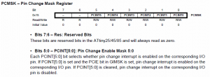
Here we can see the bits which correspond to the different pins on the ATtiny85.
sbi(PCMSK,PCINT4);
As our button is on digital pin 4 (PB4) we will enable PCINT4. You might think we could also enable it for the clock pin however as we have a resistor divider it’s not a digital “1” or “0” signal so it won’t work. Last but not least, we’ll check out I-bit of the SREG register.
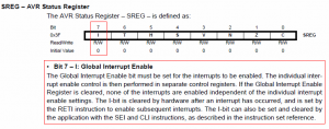
It appears this I-bit controls the global interrupt enable, if it’s not enabled that there will be no interrupts allowed. It also mentions that this I-bit is cleared after an interrupt occurs. So we should call sei() before sleep and after the sleeping is done we should call cli(), this will enable and disable the I-bit in SREG. If I-bit is left enabled (i.e cli isn’t called) then the interrupts will always be enabled and if a pin changes even when your code is running, it will jump to the PCINT0 interrupt vector.
After some testing I’ve actually found that we don’t need to use sei() because this seems to be already executed for us. To this theory we can use avr-objdump.exe to decompile our code to assembly and see if we can find any sei() or a reti() command. A reti command is used to return from an interrupt vector and also re-enables the global interrupt; it should be the last thing called (this is done by the C++ code when we define an interrupt so we don’t need to worry about it)
On the Arduino software, press Shift and then Compile and it will show you where the temporary compiled files are being stored. Navigate to that directory and then copy over the .elf file to C:\Program Files\arduino-0021\hardware\tools\avr\bin.
avr-objdump.exe -S filenamehere.cpp.elf > asm.txt
Run the above command and a file called asm.txt will be created with a lot of contents.
digitalWrite(pinLed,HIGH);  // let led blink
 96:    80 91 60 00     lds    r24, 0x0060
 9a:    61 e0           ldi    r22, 0x01    ; 1
 9c:    d0 d0           rcall    .+416        ; 0x23e <digitalWrite>
For the example above we see the C++ code to enable the pinLed to HIGH and then it shows you the resulting code to make that happen in assembly.
...
void init()
{
 // this needs to be called before setup() or some functions won't
 // work there
 sei();
 1dc:    78 94           sei
...
00000096 <__vector_2>:
ISR(PCINT0_vect) {
 96:    1f 92           push    r1
 98:    0f 92           push    r0
 9a:    0f b6           in    r0, 0x3f    ; 63
 9c:    0f 92           push    r0
 9e:    11 24           eor    r1, r1
}
 a0:    0f 90           pop    r0
 a2:    0f be           out    0x3f, r0    ; 63
 a4:    0f 90           pop    r0
 a6:    1f 90           pop    r1
 a8:    18 95           reti
...
All we need to do is go searching around for sei or reti and what do you know we find them! Sei was found when initialising the microcontroller and reti was found at the end of our interrupt. So lets put all of this pin change code into our project.
void setup() {
 pinMode(ledPin, OUTPUT);
 pinMode(buttonPin, INPUT);
 pinMode(dataPin, OUTPUT);

 // Pin interrupt setup
 sbi(GIMSK,PCIE); // Enable pin change interrupt
 sbi(PCMSK,PCINT4); // Apply to pin 4 (button)
}
We firstly modify our setup function.
ISR(PCINT0_vect) {
 f_pin = 1; // Set global flag
}
We set-up the interrupt vector. Now to save some power we can add the system_sleep function when we are waiting for input from the user.
// Always reset variables just in case
digitalWrite(ledPin, LOW);
digitalWrite(dataPin, LOW);

system_sleep();

// First test we are connected to the Arduino
int clockState = analogRead(clockPin);
if (clockState >= 160) {
....
else {
  // Button was pressed, if still pressed after 500ms,
  // check again after 1500ms, if still pressed go to configuration
  //int buttonState = digitalRead(buttonPin);
  //if (buttonState == HIGH) {
  delay(500);
  int buttonState = digitalRead(buttonPin);
  if (buttonState == true) {
...
We can actually add system_sleep right before we check for any inputs so the microcontroller will now sleep until a pin changes. What I’ve done is take the approach to check the clock pin to see if it’s connected to the Arduino. If we don’t have it connected to the Arduino then we just jump to the button checking part.
while (waitCounter != waitTime) {
  system_sleep();
  waitCounter++;
  if (f_pin == 1) {
    functionSelect = 0;
    //Disable the watchdog
    MCUSR &= ~(1<<WDRF);
    WDTCR |= (1<<WDCE) | (1<<WDE);
    WDTCR = 0;
    waitCounter = waitTime; // break out of the loop
    for (int x = 0; x < 3; x++) {
      digitalWrite(ledPin, HIGH);
      delay(250);
      digitalWrite(ledPin, LOW);
      delay(250);
    }
  }
}
Now we modify our while loop when it’s logging the temperature. So when f_pin is equal to 1 we know that either the button was pressed. We then know that it wasn’t the watchdog, so we break out of the while loop and go back to our “listening mode”. What you’ll also notice is that we have 3 lines used to disable the watchdog as per on the Atmel ATtiny85 datasheet. If we don’t disable the watchdog then it will continually run in the background which means once we go back to “listening mode” as there is a system_sleep() there, it will actually interrupt that and then begin logging the temperature.
We now need to keep in mind that when we want the ATtiny to communicate with the Arduino, we have to firstly plug the data and clock lines in and then press the button. It will then detect the clock line as HIGH and begin the communication.
// Button was pressed
int buttonState = 0;
int buttonCount = 0;
int buttonPressed = 0;
long resetTimer = millis();
while (millis() < resetTimer + 1500) {
  buttonState = digitalRead(buttonPin);
  if (buttonState == HIGH) {
    buttonCount++;
    while (buttonState == HIGH && millis() < resetTimer + 1500) {
      buttonState = digitalRead(buttonPin);
      buttonPressed++;
      delay(50);
    }
  }
}

if (buttonCount == 3) { // Start logging
  functionSelect = 1;
  dataCount = 1;
  for (int x = 0; x < 3; x++) {
   digitalWrite(ledPin, HIGH);
   delay(500);
   digitalWrite(ledPin, LOW);
   delay(500);
  }
}
else if (buttonPressed >= 20) { // Change delay time
  functionSelect = 2;
  delayTime = -1;
  digitalWrite(ledPin, HIGH);
  delay(2000);
  digitalWrite(ledPin, LOW);
}
As a precaution to prevent overwriting the data we have logged because it’s very easy to do so, before you can begin logging data I’ve made it so you need to press the button 3 times in a row within 1.5 seconds, otherwise nothing will happen.
Bug fix: We need to always call setup_watchdog before sleeping
Whilst I was playing around with the watchdog I found that the watchdog timing became erratic when incrementing a delay time for an LED to light up. Example code is below.
int dtime = 500;

void setup(){
 pinMode(pinLed,OUTPUT);
 setup_watchdog(7); // 2 seconds sleep
}

void loop(){
 digitalWrite(pinLed,HIGH);
 delay(dtime);
 digitalWrite(pinLed,LOW);
 dtime = dtime + 500;
 system_sleep();
}
What would happen is if I set the time out to 2 seconds each increment of the delay time by 500 would cause the time out to lower. After about 3 blinks of the LED it was almost down to half a second.
while (waitCounter != waitTime) {
  setup_watchdog(8);
  system_sleep();
  ...
}
To correct this issue I relocated setup_watchdog(8) to occur just before system_sleep() which seems to have corrected the issue.
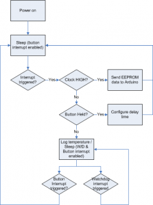
Flowchart
Here’s a flowchart which shows a basic breakdown of how our temperature logger now works.
Download
Here is our new version: Standalone_Temperature_Logger_for_ATtiny85_v1.3a
- Once power is connected it will enter sleep mode
- You need to press the button 3 times in 1.5 seconds to activate the temperature logging. The LED will blink three times.
- You need to hold the button down for 1.5 seconds to change the logging time (e.g. every 1 minute, 5 minutes, etc). The LED will stay one for 2 seconds. Configure the delay time by press the button, then hold the button down to confirm your delay time and the LED will blink three times.
- To transfer the data to the Arduino, first connect the wires and then press the button once. The LED will blink twice.
- To exit the temperature logging, hit the button once and the LED will blink 2 times
Thanks for reading Part 8! I’m hoping in Part 9 that the PCB should be ready for show. I do have the design done, I’m actually just waiting on the coin cell battery holder to arrive by post.
Edit: I found that using wdt_disable() caused a bug that wouldn’t allow you to escape the temperature logging in some rare cases, this has been corrected with v1.3a. I believe it was caused because wdt_disable() modifies the SREG register which per the Atmel ATtiny85 datasheet example it doesn’t specify doing any to SREG.





Hi,
I am struggling to get an RFM69 to work with an ATTiny84. I did look at Nathan Chantrell post, and even made the board, but I get nothing. He did use an RF12, but I added the following line, which should apparently work. #define RF69_COMPAT 1
I have got a gateway and node working using a number of different Arduino’s, but jest can’t get the tiny to communicate.
Have you managed to successfully get the RFM69 working with an ATTiny?
Thanks and regards,
Markus
Hi Markus,
I haven’t had any dealings with the RFM69 before, I use the Si4432 instead.
For the ATtiny, are you using the Arduino core for that or have you de-Arduino’ed the code to suit?
I know of someone who has used the RFM69 before, Martin over at Harizanov (example post – https://harizanov.com/2015/11/rfm69-to-mqtt-gateway-using-esp8266/)