I bet you were expecting to see Part 3 of this build? I’ve recently learned about the important of power dissipation when giving my circuit the real test of 12 volts @ 0.75 Amps and thought I’d share it with you.
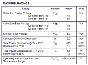
In my selection of transistors for the motor controller I went with ones that firstly had a low Vce and then based on price after that; what I didn’t completely take into account is the power dissipation of these components. I know I mentioned it in part 1 however I didn’t completely understand why one of my transistor’s datasheets had 2 values for power dissipation… and now I do, and you will to!
We’re going to ignore the “Derate above 25C” section because this isn’t a regular thing in many datasheets and focus on the “Total Power Dissipation @ Ta” and “Total Power Dissipation @ Tc”. This transistor is just a small signal transistor, the transistors that come into everyone’s mind when they think of one. When I first looked at the data sheet, the bigger number was what I had to play around with, but I was wrong.
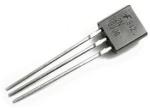
“Ta” stands for Junction to Ambient and “Tc” stands for Junction to Case. The “Junction” is inside the transistor and is the inside part that emits the most heat so naturally this is what we compare things to when doing power dissipation calculations. For Junction to Ambient we map the rate between the junction and the ambient temperature; ambient temperature is just the temperature surrounding the component, in this specific case it’s 25C. For Junction to Case it’s the map between the junction and the case temperature, the case is the transistors shell (the black part in the above picture).
Now you begin to understand the reason we can’t use Junction to Case is because the heat from the transistor doesn’t just stay at the case, it dissipates to the external environment which is heavily affected by the ambient temperature. Junction to Case is only useful if you are actually mounting a heat sink to the transistor, in our case we aren’t because we are keeping costs down. Some power transistor datasheets will only show Tc because they assume you’ll mount a heat sink, in the datasheet you’ll clearly be able to tell the transistor has a piece of metal with a hole for this heat sink.
So what’s the use of Ta you say? Ta allows us to calculate how much milliWatts (mW) we can safely use the transistor at a ambient temperature we choose. The maximum junction temperature (Tjunction) for almost all transistors is 150C. So we use a neat little formula to give us what’s called the Thermal Resistance. With the thermal resistance we’ll be able to calculate how much mW we can use at a certain temperature or vice versa.
Thermal Resistance = (Tjunction – Ambient temperature) / Power Dissipation mW (Pd @ Ta)
Thermal Resistance = (150C – 25C) / .625mW
Thermal Resistance = 200.
Do you see what we’ve done above? The Tjunction is 150C as for almost all transistors, we minus that with the Ambient temperature that the power dissipation was calculated at which is normally always 25C. Then we divide that by the Power Dissipation, Junction to Ambient (Ta). Lets assume we have a Vce of 1 Volt and we are running 0.55 Amps across the collector and emitter so we get 1V x 0.55A = 0.55 mW, so we are below our maximum of 0.625mW though fairly close.
Lets think for a bit, we can’t expect our transistor to run in 25C ambient temperature environments all the time right? So the standard temperature that most people test for is up to 50C, so lets do that calculation. By switching up the formula we now have our new formula as below.
Calculate Power Dissipation at a given Ambient temperature
Power Dissipation mW (Pd @ Ta) = (Tjunction – Ambient temperature) / Thermal Resistance
Power Dissipation mW (Pd @ Ta) = (150C – 50C) / 200
Power Dissipation (Pd @ Ta) = 0.5 mW
Wow, we now see what increasing the temperature has done, if we ran our 1 Volt and 0.55 Amps, we would be running past the rated mW and therefore the Tjunction temperature would be over 150C so the transistor will be damaged. If we wanted to see how much our Tjunction was at if we were running at 50C ambient if we were to use the 0.55mW from our 1V and 0.55A we use the formula below.
Calculate Tjunction at a given Power Dissipation and Ambient temperature
Tjunction = Power Dissipation mW (Pd @ Ta) x Thermal Resistance + Ambient temperature
Tjunction = (0.55mW x 200) + 50C
Tjunction = 110C + 50C
Tjunction = 160C
How about if we want to find the highest ambient temperature the transistor can take whilst still giving us 0.55mW? We use the formula below.
Calculate Maximum Allowable Ambient temperature at a given Power Dissipation
Ambient temperature = Tjunction – Power Dissipation mW (Pd @ Ta) x Thermal Resistance
Ambient temperature = 150C – (0.55mW x 200)
Ambient temperature = 40C
It’s a lot to take in but keep re-reading it and I’m sure you’ll get it. I hope you, like I, have learned the importance of power dissipation of transistors, how we should calculate dissipation for different ambient temperature and how all electronics components lose their effectiveness if the temperature increases. Now to correct my initialise mistake I’ve found a transistor which does 1.2W @ Ta however it’s out of stock! Hopefully the next part will be the PCB design unless I find more mistakes! 🙂


