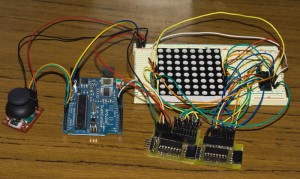
So I’ve been playing with the LED Matrix for a little while and decided a few weeks ago to make a breakout board for it. There are 3 versions of breakout board, all of which can be connected together so you can send your outputs for each register via just 3 wires. Now you can save time wiring the shift registers on your bread board.
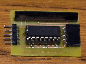
The first version is the the basic Shift Register Breakout Board.
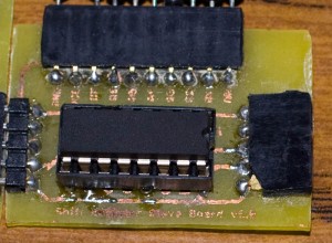
Next version is the Shift Register Slave Breakout Board which is smaller, has room so you can make the headers horizontal (for connecting to other boards) and takes out the 3 wires to communicate to the shift register. An example of another board it could connect to would be a ULN2803A board which I’m planning on making.
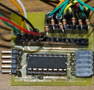
The last version is the Shift Register Resistor Board which is like the basic version however we have an extra 2 headers, so you join resistors across it and then connect to the device you wish to output to. For this version I suggest using 1/4W resistors as the 1/8W resistors wires sometimes don’t always contact the female header and move around a bit.
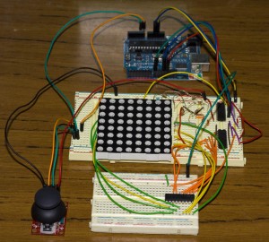
Below is before shot when using the bread board and an after shot when using the Shift Register Breakout Board. (Eventually the ULN2803A pictured on the bread board will be on a PCB which connects to the Shift Register Breakout Board). Sure it looks like it has more wires, but in reality it doesn’t.
Before
After
Schematic, designs to make your own PCB, etc are coming in the next day or so.
Edit: All details are now available here: https://www.insidegadgets.com/projects/shift-register-breakout-board/
