Welcome to Part 6, it’s been a long project so far and we are coming close to the end. In this part we’ll explain how and why we need to change our circuit and code from 5V to run at least at 1.8V.
The reason being because of communication between the Arduino and ATtiny, if you were to run the ATtiny at 1.8V and hook up the Arduino to it, the ATtiny Digital or Analog input can only go to a maximum of 1.8V. So you’re feeding 5V from the Arduino to the ATtiny at 1.8V, you’ll overload the inputs and are highly likely to damage the chip.
How can we connect both microcontrollers together if they operate at different voltages?
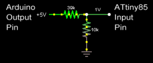
Option 1: If you recall from Part 4 we learned about voltage dividers, we can use this technique to divide the voltage in such a way that the Arduino’s 5V output can be divided to lower voltage. We can use a 39K resistor along with our already 10K resistor
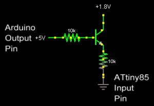
Option 2: Another technique we could employ is to use a transistor which would connect from VCC to the input pin and be triggered by the Arduino’s output pin.
We have a 2 wire connection to the Arduino, the clock which goes from the Arduino to the ATtiny and the data which goes from the ATtiny to the Arduino. We don’t need to worry much about the data other than just changing the digital pin for an Analog pin because it would be 1.8V going into 5V which is fine. For the clock, we’ll select the voltage divider option 1 because it’s less parts and thus cheaper. The configuration will be 39k with the standard 10k pull down to ground.
Lets do the calculations to find what the minimum analog value we should expect on the ATtiny for the clock pin. We want to be able to operate the ATtiny between the recommended 1.8V to 5.5V and have this still work, so we choose the highest voltage: 5.5V highest voltage / 1024 analog divisions = 0.00537 volts per division. The higher voltage we go, the lower the number per division. After the voltage divider we have 1V input from the voltage divider circuit / 0.00537 volts per division = 186 analog value. Lets give it some fluctuation and make the minimum analog value as 160.
Now for the changes to our ATtiny code: (Download Standalone_Temperature_Logger_ATtiny85_v1.1)
- We leave int clockPin =3; as is because the analog pin 3 is assigned the same port as digital pin 3.
- Remove pinMode(clockPin, INPUT); as it is no longer a digital pin
- Change int clockState = digitalRead(clockPin); if (clockState == HIGH) { to int clockState = analogRead(clockPin); if (clockState >= 160) {
- Change clockIn = digitalRead(clockPin); while (clockIn == LOW && inTransfer == true) { to clockIn = analogRead(clockPin); while (clockIn == 0 && inTransfer == true) { because we are waiting for a low value of analog read, i.e 0.
Now for the Arduino’s side: 5V constant voltage / 1024 = 0.00488 volts per division. ATtiny will supply at least 1.8V / 0.00488 = 368 analog value, we’ll make that 350.
And the changes to our Arduino code: (Download Standalone_Temperature_Logger_Reader_Arduino_v1.1)
- Change int dataPin = 3; to int dataPin = 0;
- Remove pinMode(dataPin, INPUT);
- Change all digitalRead(dataPin); to analogRead(dataPin);
- Change all dataIn == HIGH to dataIn >= 350
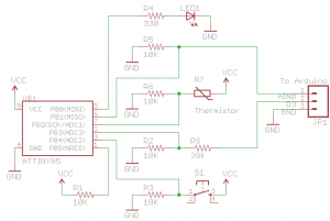
It should all be good to go, our new schematic is below.
I’ve done some testing and it appears to be all operational, we receive close to 1V (0.99V) in the clock pin on the ATtiny85. When running the ATtiny from batteries you need to remember to connect the ATtiny’s ground with the Arduino’s ground. This part was a little short but in the part we’ll cover how we can reduce our power consumption which will actually allow us to use a 3V coin cell instead of the 2 AA batteries!


Great examples
“Standalone_Temperature_Logger_ATtiny85_v1.1” came up “404” for me
Thanks, I have just updated the link to http://www.insidegadgets.com/wp-content/uploads/2011/02/Standalone_Temperature_Logger_ATtiny85_v1.1.zip