So the Arduino software has been easy to use but I’m thinking about using V-USB in one of my projects. V-USB is an implementation of the USB protocol that can run on an Atmel AVR microcontroller but in order to integrate it into one of my projects it’s time to move away from the Arduino software.
I’ll show you how we can create our own version of the ATtiny45/85 Blink without the Arduino software. We will use setup/timer functions from the internal Arduino wiring.c file because it’s easier to use something that works.
First thing we’ll do is download WinAVR from http://winavr.sourceforge.net. After installation, the default directory is C:\WinAVR-20100110.
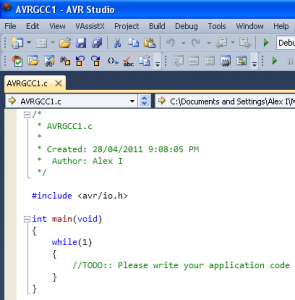
But before we start with WinAVR we need a starting template, so what I did was download AVR Studio 5 Beta and start a new blank project. The reason I’m using Programmers Notepad instead of AVR Studio is that it’s a very simple interface and from my testing actually compresses things better when compiling.
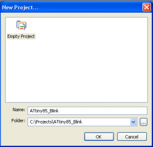
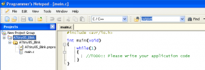
Now we’ll open up Programmers Notepad (referred to as PN) from Start -> All Programs -> WinAVR-20100110 -> Programmers Notepad [WinAVR] and start a new project call it ATtiny85_Blink in a new directory. Make sure the directories in between don’t have spaces in them, e.g. C:\my projects\ATtiny85_blink would cause issues.
#include <avr/io.h>

int main(void)
{
  while(1)
  {
    //TODO:: Please write your application code
  }
}
Let’s create our main file called main.c and put the starting template code in it. The main function is the first function that is executed so it’s the place where we need to do our setup routine and then all our work will be done in the while loop. Save the main.c file in the directory we created our project in (C:\Projects\ATtiny85_Blink).
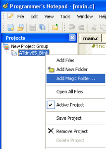
Now we want to see the all the files/folders contained in our project. Right click on the project name and select Add Magic Folder then choose the folder where the project is at.
Now all the files are shown.
Create the Makefile to compile your project
So it’s all good that we have some code but we have to be able to compile our code into a .hex file which we can program our ATtiny85 with; this is where the makefile comes in. It’s basically a file that has rules which assembles all of our code together with.
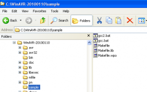
Luckily for us there is actually a template Makefile that comes with WinAVR which is located at C:\WinAVR-20100110\sample. Go ahead and copy that to your project directory.
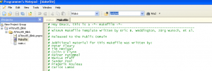
Now open up the Makefile in PN as we need to make some slight modifications. You will have to refresh the directory in PN to see it.
# MCU name
MCU = attiny85
First thing we need to do is change the MCU to the attiny85 or 45 which ever one you are using.
#F_CPU = 1000000
The next thing is the CPU speed, the ATtiny85 defaults to 1MHz so we should change it to 1000000, however I actually put this in the main.c file instead to allow for easy access as I don’t want to touch the Makefile again once it’s set so I have commented this out.
#define F_CPU 1000000
We need to jump back to the main.c file and add the above define at the top. Define just says that if the compiler sees any references to F_CPU the value is 1000000.
Just a fact about F_CPU, it doesn’t actually determine the microcontroller’s MHz speed but it’s used for calculating delays. It does this by looking at the clock cycles, a 1MHz clock cycle is 1,000ns whilst 2MHz is 500ns. The delay function takes this and calculates how many clock cycles it would need to wait for x amount of time.
This is to say that if your microcontroller was running at 2MHz but your F_CPU was at 1MHz, a delay of 10ms would really be 5ms. Just something to keep note of if you ever need to change your microcontrollers speed whilst it’s running.
 #---------------- Programming Options (avrdude) ----------------

# Programming hardware
# Type: avrdude -c ?
# to get a full listing.
#
AVRDUDE_PROGRAMMER = stk500v1
Next we change the programmer being used. If you are using the Arduino as the ISP like I am, you change it to stk500v1.
 # com1 = serial port. Use lpt1 to connect to parallel port.
AVRDUDE_PORT = com2    # programmer connected to serial device
Also change the COM port.
AVRDUDE_BITS_PER_SEC = -b 19200

AVRDUDE_FLAGS = -p $(MCU) -P $(AVRDUDE_PORT) -c $(AVRDUDE_PROGRAMMER)
AVRDUDE_FLAGS += $(AVRDUDE_NO_VERIFY)
AVRDUDE_FLAGS += $(AVRDUDE_VERBOSE)
AVRDUDE_FLAGS += $(AVRDUDE_ERASE_COUNTER)
AVRDUDE_FLAGS += $(AVRDUDE_BITS_PER_SEC)
Another thing I’ve added is to limit the bytes per second to 19200, so you will need to add above and in the AVRDUDE_FLAGS right at the end if you are using Arduino as the ISP.
 # Define programs and commands.
SHELL = sh
CC = /c/WinAVR-20100110/bin/avr-gcc
OBJCOPY = /c/WinAVR-20100110/bin/avr-objcopy
OBJDUMP = /c/WinAVR-20100110/bin/avr-objdump
SIZE = /c/WinAVR-20100110/bin/avr-size
AR = /c/WinAVR-20100110/bin/avr-ar rcs
NM = /c/WinAVR-20100110/bin/avr-nm
AVRDUDE = /c/WinAVR-20100110/bin/avrdude
This part really depends on your setup. I actually had another instance of PN which I used fro something else so to keep them separate I change the location of these files to point directly to the WinAVR folder instead of looking at the Windows PATH environment. It’s very likely that you won’t have to do anything here.
View the complete Makefile here: Makefile
Setup functions
Now we’ll create a setup.c file where all of our setup functions will be.
 #ifndef cbi
  #define cbi(sfr, bit) (_SFR_BYTE(sfr) &= ~_BV(bit))
#endif
#ifndef sbi
  #define sbi(sfr, bit) (_SFR_BYTE(sfr) |= _BV(bit))
#endif
First we add the cbi and sbi defines which you might remember from my previous projects. Sbi turns on a bit and cbi turns that bit off which are useful when accessing the microcontrollers registers.
#ifndef boolean
  typedef uint8_t boolean;
#endif
#ifndef byte
  typedef uint8_t byte;
#endif
The Arduino programming language used the boolean and byte type but WinAVR doesn’t have these by default. What we do is if any of our code mentions either, we define the type as a uint8_t which just means it’s an 8 bit unsigned number, i.e. range is 0 to 255 (11111111)
// START Arduino wiring.c - to use the timers
#define clockCyclesPerMicrosecond() ( F_CPU / 1000000L )
#define clockCyclesToMicroseconds(a) ( (a) / clockCyclesPerMicrosecond() )
...
//different name, TIMER0_OVF_vect to this
SIGNAL(TIM0_OVF_vect)
{
...
}

unsigned long millis(void) {
...
}
// END Arduino wiring.c
Now it’s time for us to grab some timer functions from the Arduino’s wiring.c file. I haven’t listed all of the code we have used but just note that all this code is needed if you call millis() and it’s another way for us to use the timers instead of just using delay_ms().
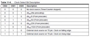
The basic theory to the timer is that once every x clock cycles you can make the timer counter increment by 1. You can have it divide the clock by 1, 8, 64, 256, 1024,etc so it would increment quicker or faster depending on the accuracy you want, this is what’s called the prescaler.
We are using an 8 bit timer so when the timer reaches 255 (256 values), it “overflows” and goes back to 0. Every time it overflows we can stick an interrupt to catch the event and to increment a variable which we can then use to calculate how many milliseconds have passed. There is a PDF from Atmel which explains it all in detail.
For example, we set the prescaler to 64, use an 8 bit timer and are using a microcontroller set to 1MHz we can find out how many milliseconds will pass until an overflow happens:
64 prescaler x 256 values / 1 MHz / 1000 = 16.384ms for each overflow
This means that if we were counting the milliseconds in our own overflow variable, it would only ever increment every 16ms which would be a concern if you needed precise timing of a few milliseconds. For us it’s not a concern as we will just be blinking an LED every second.
If it was a concern you can set the prescaler to 1 which would give you 0.256ms for each overflow.
1 prescaler x 256 values / 1 MHz / 1000 = 0.256 ms
// Used from Arduino wiring.c - to setup the ATtiny
void setup(void) {
  sei(); // Turn on interrupts
The next part we also use from Arduino’s wiring.c file, this time it’s the actual setup of the microcontroller. First we turn on the interrupts.
/* dumpt everything, and only added the 2 timers the attiny has */
// on the ATmega168, timer 0 is also used for fast hardware pwm
// (using phase-correct PWM would mean that timer 0 overflowed half as often
// resulting in different millis() behavior on the ATmega8 and ATmega168)
sbi(TCCR0A, WGM01);
sbi(TCCR0A, WGM00);
// set timer 0 prescale factor to 64
sbi(TCCR0B, CS01);
sbi(TCCR0B, CS00);
// enable timer 0 overflow interrupt
sbi(TIMSK, TOIE0);
Next they configure the timer registers. WGM01 and WGM00 configure the timer to overflow and then CS01 and CS00 set the prescaler to 64, then turn on timer 0 which will be used for the millis.
// timers 1 are used for phase-correct hardware pwm
// this is better for motors as it ensures an even waveform
// note, however, that fast pwm mode can achieve a frequency of up
// 8 MHz (with a 16 MHz clock) at 50% duty cycle
// set timer 1 prescale factor to 64
sbi(TCCR1, CS12); // Inside Gadgets fix
sbi(TCCR1, CS11);
sbi(TCCR1, CS10);
sbi(TCCR1, PWM1A);
Next they turn on timer1 for PWM, this isn’t needed for our example but we’ll leave it in anyway. CS12, CS11, CS10 select the prescaler as 64 for this timer.
// set a2d prescale factor to 128
// 16 MHz / 128 = 125 KHz, inside the desired 50-200 KHz range.
// XXX: this will not work properly for other clock speeds, and
// this code should use F_CPU to determine the prescale factor.
/* added F_CPU prescaler */
#if F_CPU >= 16000000L //128
sbi(ADCSRA, ADPS2);
sbi(ADCSRA, ADPS1);
sbi(ADCSRA, ADPS0);
#elif F_CPU >= 8000000L //64
sbi(ADCSRA, ADPS2);
sbi(ADCSRA, ADPS1);
#else                //8
sbi(ADCSRA, ADPS1);
sbi(ADCSRA, ADPS0);
#endif
// enable a2d conversions
sbi(ADCSRA, ADEN);
}
Lastly according to the ATtiny85 datasheet page 129 the Analog to Digital (ADC) frequency range needs to be 50-200KHz, since we are at 1MHz they enable it to device by 8, so it would be 125KHz. If you were at 2MHz you should keep an eye on this because you would be at 250KHz and lastly they turn on the ADC. This isn’t needed once again but I will leave it is so it’s ready to be used if you need it.
The setup.c file is now done but we need to make a reference to it from the main.c file.
#include "setup.c"
What we do is add an include to the setup.c file, note it’s in brackets to signify that it’s a local file.
#include <avr/interrupt.h>
#include <util/delay.h>
Since we are using interrupts and the delay function we need to include the two header files for those functions.
int main(void) {
  setup();
Then we call it from the main function.
View the complete setup.c file here: setup
Main Blinking Code
// ATtiny45/85 Pin map
//                        +-\/-+
// Reset/Ain0 (D 5) PB5  1|o   |8  Vcc
//       Ain3 (D 3) PB3  2|    |7  PB2 (D 2) Ain1
//       Ain2 (D 4) PB4  3|    |6  PB1 (D 1) pwm1
//                  GND  4|    |5  PB0 (D 0) pwm0 <-- connect LED here
//                        +----+

#define ledPin PB0
To make things simpler, we define ledPin as PB0 which is where our LED will be connected.
int main(void) {

  setup();

  DDRB |= (1<<ledPin); // Set LED as an output

  while(1) {

    // Delay 1 second using delay_ms
    PORTB |= (1<<ledPin); // Turn on
    _delay_ms(1000);
    PORTB &= ~(1<<ledPin); // Turn off
    _delay_ms(1000);
Now we set PB0 as an output by using DDRB and setting it to 1 (If you haven’t used DDRB before I recommended the Arduino Port Manipulation page out). Next we go into the while loop and use PORTB to turn on our LED, use _delay_ms to delay by 1000 milliseconds and then turn off the LED and delay another 1000ms.
    // Delay 1 second using the timer
    long resetTimer = millis();
    PORTB |= (1<<ledPin); // Turn on
    while (millis() < resetTimer + 1000) { }
    PORTB &= ~(1<<ledPin); // Turn off
    resetTimer = millis();
    while (millis() < resetTimer + 1000) { }
  }
}
Now we do the same thing using millis(). We assign a variable with the current milliseconds, turn on the LED and use a while loop to check when millis() is greater than 1 second more than the value we stored in our variable. After about 1 second it will then turn the LED off and then do the same thing to wait another second before it jumps back to the while loop.
Download the full source here: ATtiny85_Blink_v1.0
Compile and Run
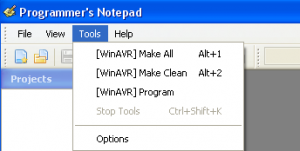
Next you compile by going to Tools -> Make All and can upload to your ATtiny45/85 by going to Tools -> Program.
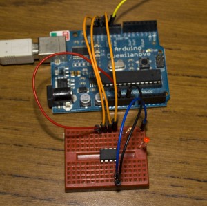
And of course it works!
So that’s it, now we aren’t using the Arduino software and we can still code. While it’s not as simple as using the Arduino software eventually you will get used to it. By switching to WinAVR directly most of the time you should see a slight reduction in the size of your compiled code and now be able to distribute your entire code without the need of the end user needing the Arduino software.
Move from Arduino software to WinAVR with Programmers Notepad
So the Arduino software has been easy to use but I’m thinking about using V-USB which is an implementation of USB that can run on an Atmel AVR microcontroller so in order to integrate it into one of my projects it’s time to move away from the Arduino software.
I’ll show you how we can create our own version of the ATtiny45/85 Blink without the Arduino software however we will use setup/timer functions from the internal Arduino wiring.c file because it’s easier to use something that works.
First thing we’ll do is download WinAVR from http://winavr.sourceforge.net. After installation, the default directory is C:\WinAVR-20100110.
#include
<avr/io.h>

int
main(void)

{

<span>    </span>while(1)

<span>    </span>{

<span>   </span><span>     </span>//TODO:: Please write your application
code

<span>    </span>}

}
But before we start with WinAVR we need a starting template, so what I did was download AVR Studio 5 Beta and start a new blank project. The reason I’m using Programmers Notepad instead of AVR Studio is that it’s a very simple interface and from my testing actually compresses things better when compiling.
czxczxcxc
Now we’ll open up Programmers Notepad (referred to as PN) from Start -> All Programs -> WinAVR-20100110 -> Programmers Notepad [WinAVR] and start a new project call it ATtiny85_Blink in a new directory. Make sure the directories in between don’t have spaces in them, e.g. C:\my projects\ATtiny85_blink would cause issues.
zxczxc
Let’s create our main file called main.c and put the starting template code in it. The main function is the first function that is executed so it’s the place where we need to do our setup routine and then all our work will be done in the while loop. Save the main.c file in the directory we created our project in (C:\Projects\ATtiny85_Blink)
Zxczxcc
Now we want to see the all the files/folders contained in our project. Right click on the project name and select Add Magic Folder then choose the folder where the project is at.
czxczxc
Now all the files are shown.
Create the Makefile to compile your project
So it’s all good that we have some code but we have to be able to compile our code into a .hex file which we can program our ATtiny85 with, this is where the makefile comes in. It’s basically a file that has rules which assembles all of our code together with.
zxczxcxc
Luckly for us there is actually a template Makefile that comes with WinAVR which is located at C:\WinAVR-20100110\sample. Go ahead and copy that to your project directory.
zxczxczxc
Now open up the Makefile in PN as we need to make some slight modifications. You will have to refresh the directory in PN to see it.
# MCU
name

MCU =
atmega128
First thing we need to do is change the MCU to the attiny85 or 45 which ever one you are using.
#F_CPU
= 8000000
The next thing is the CPU speed, the ATtiny85 defaults to 1MHz so we should change it to 1000000, however I actually like to put this in the main.c file instead to allow for easy access as I don’t want to touch the Makefile again once it’s set so I have commented this out.
#define
F_CPU 1000000
We need to jump back to the main.c file and add the above define at the top. Define just says that if the compiler sees any references to F_CPU the value is 1000000.
Just another fact about this F_CPU, it doesn’t actually determine the microcontroller’s MHz speed but it’s used for calculating delays. It does this by looking at the clock cycles, a 1MHz clock cycle is 1,000ns whilst 2MHz is 500ns. The delay function takes this and calculates how many clock cycles it would need to wait for x amount of time.
This is to say that if your microcontroller was running at 2MHz but your F_CPU was at 1MHz, a delay of 10ms would really be 5ms, something to keep note of if you ever need to change your microcontrollers speed whilst it’s running.
 #----------------
Programming Options (avrdude) ----------------

#
Programming hardware

# Type:
avrdude -c ?

# to get a
full listing.

#

AVRDUDE_PROGRAMMER
= stk500v1
Next we change the programmer being used. If you are using the Arduino as the ISP like I am, you change it to stk500v1.
 #
com1 = serial port. Use lpt1 to connect to parallel port.

AVRDUDE_PORT
= com2<span>    </span># programmer connected to
serial device
Also change the COM port.
AVRDUDE_BYTES_PER_SEC
= -b 19200

AVRDUDE_FLAGS
= -p $(MCU) -P $(AVRDUDE_PORT) -c $(AVRDUDE_PROGRAMMER)

AVRDUDE_FLAGS
+= $(AVRDUDE_NO_VERIFY)

AVRDUDE_FLAGS
+= $(AVRDUDE_VERBOSE)

AVRDUDE_FLAGS
+= $(AVRDUDE_ERASE_COUNTER)

AVRDUDE_FLAGS
+= $(AVRDUDE_BYTES_PER_SEC)
Another thing I’ve added is to limit the bytes per second to 19200, so you will need to add above and in the AVRDUDE_FLAGS right at the end if you are using Arduino as the ISP.
 #
Define programs and commands.

SHELL = sh

CC =
/c/WinAVR-20100110/bin/avr-gcc

OBJCOPY =
/c/WinAVR-20100110/bin/avr-objcopy

OBJDUMP =
/c/WinAVR-20100110/bin/avr-objdump

SIZE =
/c/WinAVR-20100110/bin/avr-size

AR =
/c/WinAVR-20100110/bin/avr-ar rcs

NM =
/c/WinAVR-20100110/bin/avr-nm

AVRDUDE =
/c/WinAVR-20100110/bin/avrdude
This part really depends on your setup; I actually had another instance of PN which I used fro something else so to keep them separate I change the location of these files to point directly to the WinAVR folder instead of looking at the Windows PATH environment. It’s very likely that you won’t have to do anything here.
Setup file functions
Now we’ll create a setup.c file where all of our setups function will be,
 #ifndef
cbi

#define
cbi(sfr, bit) (_SFR_BYTE(sfr) &= ~_BV(bit))

#endif

#ifndef sbi

#define
sbi(sfr, bit) (_SFR_BYTE(sfr) |= _BV(bit))

#endif
First we add the cbi and sbi defines which you might remember from my previous projects; sbi turns on a bit and cbi turns that bit off which are useful when accessing the microcontrollers registers.
#ifndef
boolean

<span>                </span>typedef uint8_t boolean;

#endif

#ifndef byte

<span>                </span>typedef uint8_t byte;

#endif
Now Arduino programming language used the boolean and byte type but WinAVR doesn’t have these by default. What we do is if any of our code mentions either, we define the type as a uint8_t which just means it’s an 8 bit unsigned number, i.e. range is 0 to 255 (11111111)
//
START Arduino wiring.c - to use the timers

#define
clockCyclesPerMicrosecond() ( F_CPU / 1000000L )

#define
clockCyclesToMicroseconds(a) ( (a) / clockCyclesPerMicrosecond() )

…

//different
name, TIMER0_OVF_vect to this

SIGNAL(TIM0_OVF_vect)

{

<span>                </span>…

}

unsigned
long millis(void) {

<span>                </span>…

}

// END
Arduino wiring.c
Now it’s time for us to grab some timer functions from the Arduino’s wiring.c file. I haven’t listed all of the code we have used but just note that all this code is needed if you call millis() and it’s another way for us to use the timers instead of just using delay_ms().
The basic theory to the timer is that once every x clock cycles you can make the timer counter increment by 1. You can have it divide the clock by 1, 8, 64, 256 and 1024 so it would increment quicker or faster depending on the accuracy you want, this is what’s called the prescaler.
We are using an 8 bit timer so when the timer reaches 255 (256 values), it “overflows” and goes back to 0. Every time it overflows we can stick an interrupt to catch the event and to increment another counter which we can then use to calculate how many milliseconds have passed. There is a PDF from Atmel which explains it all in detail.
For example, we set the prescaler to 64, use an 8 bit timer and are using a microcontroller set to 1MHz we can find out how many milliseconds will pass until an overflow happens.
64 prescaler x 256 values / 1 MHz / 1000 = 16.384ms for each overflow
This means that if we were counting the milliseconds, it would only ever increment by 16 which would be a concern if you needed precise timing of a few milliseconds but for us it’s not a concern as we will just be blinking an LED every second.
If it was a concern you can set the prescaler to 1 which would give you 0.256ms for each overflow.
1 prescaler x 256 values / 1 MHz / 1000 = 0.256 ms
// Used from Arduino wiring.c – to setup the ATtiny
void setup(void) {
sei(); // Turn on interrupts
The next part we also use from Arduino’s wiring.c file, this time it’s the actual setup of the microcontroller and I can explain some of this, first we turn on the interrupts.
<span>   </span>/* dumpt everything, and only added the 2
timers the attiny has */

<span>                </span>// on the ATmega168, timer 0 is
also used for fast hardware pwm

<span>                </span>// (using phase-correct PWM
would mean that timer 0 overflowed half as often

<span>                </span>// resulting in different
millis() behavior on the ATmega8 and ATmega168)

<span>                </span>sbi(TCCR0A, WGM01);

<span>                </span>sbi(TCCR0A, WGM00);

<span>                </span>// set timer 0 prescale factor
to 64

<span>                </span>sbi(TCCR0B, CS01);

<span>                </span>sbi(TCCR0B, CS00);

<span>                </span>// enable timer 0 overflow
interrupt

<span>                </span>sbi(TIMSK, TOIE0);
Next they configure the timer registers and turn on timer 0 which will be used for the millis.
<span>   </span>// timers 1 are used for phase-correct
hardware pwm

<span>                </span>// this is better for motors as
it ensures an even waveform

<span>                </span>// note, however, that fast pwm
mode can achieve a frequency of up

<span>                </span>// 8 MHz (with a 16 MHz clock)
at 50% duty cycle

<span>                </span>// set timer 1 prescale factor
to 64

<span>                </span>sbi(TCCR1, CS12); // Inside
Gadgets fix

<span>                </span>sbi(TCCR1, CS11);

<span>                </span>sbi(TCCR1, CS10);

<span>                </span>sbi(TCCR1, PWM1A);
Next they turn on timer1 for PWM, this isn’t needed for our example but we’ll leave it in anyway.
<span>   </span>// set a2d prescale factor to 128

<span>                </span>// 16 MHz / 128 = 125 KHz,
inside the desired 50-200 KHz range.

<span>                </span>// XXX: this will not work
properly for other clock speeds, and

<span>                </span>// this code should use F_CPU to
determine the prescale factor.

<span>                </span>/* added F_CPU prescaler */

<span>                </span>#if F_CPU >= 16000000L //128

<span>                                </span>sbi(ADCSRA,
ADPS2);

<span>                                </span>sbi(ADCSRA,
ADPS1);

<span>                                </span>sbi(ADCSRA,
ADPS0);

<span>                </span>#elif F_CPU >= 8000000L //64

<span>                                </span>sbi(ADCSRA,
ADPS2);

<span>                                </span>sbi(ADCSRA,
ADPS1);

<span>                </span>#else<span>                                                     </span>//8

<span>                                </span>sbi(ADCSRA,
ADPS1);

<span>                                </span>sbi(ADCSRA,
ADPS0);

<span>                </span>#endif

<span>                                </span>// enable a2d
conversions

<span>                                </span>sbi(ADCSRA,
ADEN);

}
Lastly according to the ATtiny85 datasheet page 129 the Analog to Digital (ADC) frequency range needs to be 50-200KHz, since we are at 1MHz they enable it to device by 8, so it would be 125KHz. If you were at 2MHz you should keep an eye on this because you would be at 250KHz and lastly they turn on the ADC. This isn’t needed once again but I will leave it is so it’s ready to be used if you need it.
The setup.c file is now done but we need to make a reference to it from the main.c file.
#include "setup.c"
What we do is add an include to the setup.c file, note it’s in brackets to signify that it’s a local file.
int
main(void) {

<span>                </span>setup();
Then we call it from the main function.
View the complete setup.c file here: asdasdasdsad


hurray! looking forward to the continuation!
Hi,
It did not work on the first try.
I fixed this by moving the import of interrupt.h to the setup.c file.
Regards,
Arnoud
Hi Arnoud,
That’s very odd, what was happening when it didn’t work? Did the LED just stay on all the time?
What happens if you move the import of interrupt.h after the import of delay.h does that also work?
Are you using WinAVR and an ATtiny25/45/85 or something else?
Great article! Very well made and helpful
hi,
how to add the Tools> [WinAvr] Make All , make, program?
Thanks!
Hi Don,
It came like that by default for me when I downloaded WinAVR.
To add it manually go to Tools -> Options -> Tools -> Add.
Or easier yet, download this file (http://www.insidegadgets.com/wp-content/uploads/2012/05/WinAVRxml.zip) and place it in your “programmers notepad/tools” directory, then reload programmers notepad.
I wonder if you can furnish any help at all on the step of burning the program. I’m getting the old “avrdude: stk500_getsync(): not in sync: resp=0x00” error.
I’m trying to use an Arduino UNO as ISP for an ATMega328p. I’ve got the ATMega328p working correctly on its own, using a 16MHz external clock (firing away the Blink programme which came burned on it).
I omitted the setup.c file, since the ATMega’s registers don’t coincide with those of the ATTiny. (The Make step works fine, anyway.) I defined F_CPU as 16000000 (because of my external clock). In the Makefile, I set MCU = atmega328p and AVRDUDE_PROGRAMMER = stk500v1.
Any idea what I should be checking?
Assuming you programmed ArduinoISP to the Arduino Uno, I have heard that disabling the auto-reset on the Arduino Uno can help – Connect a 120 Ohm resistor from 5V to Reset. Did you also modify the makefile to change ATtiny85 to ATMega328p?
Sorry to be so inexperienced. I didn’t have the ArduinoISP sketch loaded to the programmer Arduino.
I had to make two other changes as well: [omit the pullup resistor between 5V and Reset] AND [run a wire between Reset on the receiving ATMega and pin10 on the ISP Arduino].
Thank you much, sir.
Arduino is SOOOOO easier. You plug it into usb, write a couple of lines, click upload and it works. You can now use arduino language with Attiny85… So, what is the point of Old style coding ? Maybe I just don’t see it…
Hi Frank, Yes I agree that the Arduino is easy to use.
There are many reasons to code without using the Arduino software which include:
– Using features of the MCU that the the Arduino software may not have at the moment
– Speed improvement / optimisation / saving battery life for mobile applications
– A bit more memory to play around with
– Deeper understanding/learning of how the features work on the MCU
Hello, This is an amazing article you have written, and i congratulate you for it. I seem to be having a problem whenever I compile your source file in WinAVR, I cannot “Make All”. I get an error code 2, and something written like:
——- begin ——–
process_begin: CreateProcess(NULL, /c/WinAVR-20100110/bin/avr-gcc –version, …) failed.
make (e=2): The system cannot find the file specified.
make.exe: *** [gccversion] Error 2
Can you please help me?
Hi Sampreet,
It looks like you will need to change the makefile, this happens for my old projects, you need to find any reference to /c/ in the Makefile and change it to c:/