Today I’ll be showing you one of the example projects of V-USB called EasyLogger, it’s basically a project using the ATtiny45 that logs a voltage and writes the value to your computer via USB. I choose EasyLogger because it’s very similar to the sort of things I’ll be using, i.e an ATtiny85 and no external crystal.
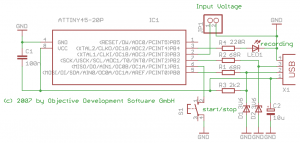
We’ll start off by downloading the latest version of EasyLogger and then viewing the schematic for it.
It looks pretty simple but to make it even simpler we’ll actually be ignoring the LED, button and input voltage so it’s just the USB connection and nothing else.
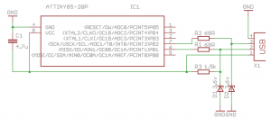
There is a new component in the schematic that I haven’t used myself or covered before which is the Zener diode. The easiest way to think of a Zener diode is like a regular diode but that is a certain voltage point called Vz where it sort of “captures” any upper voltage of the power source. An interesting way to look at is that it’s kind of a “voltage reducer”.
For example, we have a 5 volt power supply and our zener diode has a Vz of 3.6 volts. You can see that before passing the resistor its 5V, then when it reaches the zener diode its 3.6V.
Now if we change Vz to 7V which is value greater than the power supply then no current flows because the Vz limit hasn’t been reached. An application of the zener would be to use it as voltage converter to convert 5V signals into 3.3V signals (which is what we’ll actually be doing).
Let’s take a look at the USB cable specification – VBUS (VCC) provides 5V and that the data – / + lines run on 2.8-3.6V logic; lets just say 3.3V.
Above is the schematic that comes with V-USB and below that is the schematic that we will be using. It shows the VCC running to the VCC of the ATtiny so that’s running at 5V too but if we were to use any pins as outputs it would give 5V and not the 3.3V logic needed, we can now see the use of the zener diode. It’s set it up on both data lines to convert our 5V logic into 3.3V (or thereabouts). The 1.5K resistor is there to pull up the D- line.
Summary of EasyLogger with V-USB
Just a quick summary on how EasyLogger with V-USB works. First it calibrates the internal oscillator by using the USB connection for the timing. It then initialises the timer, ADC, USB and then goes on to the main loop. The main loop checks to see if we have anything to send to the computer, if so it sends the data. It pools the timer to check if 1 second has passed and if so turns on the ADC conversion. It then converts each digit of the ADC value into ASCII values and stores it in the variable to send the computer so the next time around the loop it will be received by the computer.
Makefile changes
The makefile that comes with Easylogger won’t suit our needs so I’ve just replaced it with the makefile we made in our ATtiny85 Blink test.
# Link: create ELF output file from object files.
.SECONDARY : $(TARGET).elf
.PRECIOUS : $(OBJ)
%.elf: $(OBJ) usbdrv/usbdrv.o usbdrv/usbdrvasm.o usbdrv/oddebug.o
 @echo
 @echo $(MSG_LINKING) $@
 $(CC) $(ALL_CFLAGS) $^ --output $@ $(LDFLAGS)]
One change that you’ll need to make it add the compiled usbdrv library to it, modification shown above.
Code changes
The code that comes with EasyLogger makes you press a button to begin writing the output to your computer, we’re going to bypass this and the ADC request to have it always repeat a specific number to the computer when connected.
#define F_CPU 16500000
First we need to add this to both the main.c file and the usbconfig.h files to make our ATtiny85 run fast enough to handle USB communication.
 #include <avr/io.h>
#include <avr/wdt.h>
#include <avr/eeprom.h>
#include <avr/interrupt.h>
#include <avr/pgmspace.h>
#include <util/delay.h>

#include "usbdrv/usbdrv.h"
#include "usbdrv/oddebug.h"
As the usbdrv folder is underneath our main directory we need to modify the includes to reflect this.
for(;;){    /* main event loop */
  wdt_reset();
  usbPoll();
  if(usbInterruptIsReady() && nextDigit != NULL){ /* we can send another key */
    buildReport();
    usbSetInterrupt(reportBuffer, sizeof(reportBuffer));
  if(*++nextDigit == 0xff)    /* this was terminator character */
    nextDigit = NULL;
  }
  timerPoll();
  //adcPoll();
}
Above is the main loop, we’ll just comment our the adcPoll call.
static void timerPoll(void)
{
static uchar timerCnt;
if(TIFR & (1 << TOV1)){
TIFR = (1 << TOV1); /* clear overflow */
//keyPoll();
if(++timerCnt >= 63){ /* ~ 1 second interval */
timerCnt = 0;
//if(isRecording){
//adcPending = 1;
//ADCSRA |= (1 << ADSC); /* start next conversion */
//}
}
}
}[/code]
We comment out the keyPoll call which checks to see if the button has been pressed and the check called isRecording. Also we comment out the ADC part too.
[code]static void evaluateADC(unsigned int value)
{
uchar digit;
value += value + (value >> 1); /* value = value * 2.5 for output in mV */
nextDigit = &valueBuffer[sizeof(valueBuffer)];
*--nextDigit = 0xff;/* terminate with 0xff */
*--nextDigit = 0;
*--nextDigit = KEY_RETURN;
do{
digit = value % 10;
value /= 10;
*--nextDigit = 0;
if(digit == 0){
*--nextDigit = KEY_0;
}else{
*--nextDigit = KEY_1 - 1 + digit;
}
}while(value != 0);
}
This is the part of the code that converts the ADC into ASCII the corresponding HID values. It seems to use the nextDigit variable to reference the end of the buffer. Then it minuses 1 each time it add things to nextDigit so it really enters in digits backwards as you see it terminate using 0xFF, then it puts a 0 and then key return (which is like pressing the return key). After that it runs the while loop to do the conversion, so from this we have enough to make it put any digits repeatedly.
static void timerPoll(void)
{
static uchar timerCnt;
if(TIFR & (1 << TOV1)){
TIFR = (1 << TOV1); /* clear overflow */
//keyPoll();
if(++timerCnt >= 63){ /* ~ 1 second interval */
timerCnt = 0;
//if(isRecording){
//adcPending = 1;
//ADCSRA |= (1 << ADSC); /* start next conversion */
nextDigit = &valueBuffer[sizeof(valueBuffer)];
*--nextDigit = 0xff;/* terminate with 0xff */
*--nextDigit = 0;
*--nextDigit = KEY_RETURN;
*--nextDigit = KEY_0;
*--nextDigit = KEY_1;
*--nextDigit = KEY_2;
*--nextDigit = KEY_3;
//}
}
}
}[/code]
We re-edit timerPoll and where the ADC code was we insert the nextDigit code, so when it connects to the computer it will print the digits 3210 and then the enter key.
Internal oscillator calibration
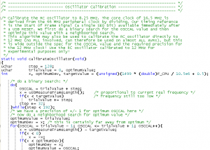
So there is a section in V-USB which it calibrates the internal oscillator and it actually mentions that the algorithm can use OSCCAL values more than 192 which could exceed the voltage of low voltage designs. Whilst this isn’t a problem for us as we are running at 5V, I was still a bit concerned about the warning so did some research.
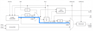
Let’s jump right into the ATtiny85 datasheet page 24, we can see the clocking system and I’ve highlighted the path that using the internal oscillator with PLL takes. We use PLL because it allows us to multiple the oscillator clock by 2 (in the end). As you can see it goes from the 8MHz oscillator, PLL when enabled times that by 8 which gives 64MHz and then is always divided by 4 to give us 16MHz.
By calibrating the internal oscillator to a higher value such as 8.25MHz which we use for V-USB, the end clock would be 16.5MHz. So let’s see how to calibrate it.
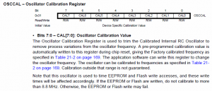
On page 32 we see that there is a register called OSCCAL which we can use to adjust the 8MHz timing. Notice the warning about calibrating to more than 8.8MHz, let’s keep this in mind.
A simple table shows us how it works in relation to the 8MHz clock, they split it into 2 x 128 chunks which the CAL7 bit is used to indicate if it’s the lower or higher chunk.
So if we used 0x3F (63) we would run the clock at 75% which gives us 6MHz. If we ran at 191 (0xBF) this means that CAL7 bit is on so we would run at 150% of 8MHz which is 12MHz. This would mean we are way beyond the warning on 8.8Mhz but this is what the original code was doing. Perhaps the original code is configured for a different MCU, nevertheless let’s fix it up so the maximum will be 8.8MHz.
As per the datasheet it says we shouldn’t change the calibration in more than 0x20 (32) steps but even then an increase or decrease of 32 is a pretty big step. We can calculate that since 0x3F (63) is 50% it would give us 0.79 for each 1%, thus a 32 digit increase in theory would give us 25% to 12MHz still too high for our 8.25MHz requirement.
But before we look at the code being used, we need to look at a graph on page 199 which shows us the oscillator frequency vs OSCCAL value. This is very important because we can clearly see that it’s not as straight cut as we would have thought. For example, our estimate of 191 being 12MHz is wrong it’s actually more like 10MHz and if we were to use an OSCCAL close to 128 like 125 or 131, I would have thought it would be very close to 8MHz but it turns out it’s not quite that way as you see. From looking at the graph our ideal values could be around 112 or 160 for a oscillator clock of 8.25MHz.
Let’s take a look at what the original code was doing. We can do this easily by moving the code to Tiny C Compiler which is a simple way run some C code. Download TCC and extract it to any directory. You compile things by running tcc <file.c> in a command prompt and then run <file>.exe.
#include
#include
#include
int main(int argc, char **argv) {
int OSCCAL = 0;
int step = 128;
int trialValue = 0, optimumValue;
int x;
/* do a binary search: */
do{
OSCCAL = trialValue + step;
//x = usbMeasureFrameLength(); /* proportional to current real frequency */
//if(x < targetValue) /* frequency still too low */
trialValue += step;
step >>= 1;
printf(“OSCCAL = %i, trialValue = %i, step = %i\n”, OSCCAL, trialValue, step);
}while(step > 0);
printf(“Binary search done\n”);
/* We have a precision of +/- 1 for optimum OSCCAL here */
/* now do a neighborhood search for optimum value */
for(OSCCAL = trialValue – 1; OSCCAL <= trialValue + 1; OSCCAL++){
//x = usbMeasureFrameLength() - targetValue;
if(x < 0)
x = -x;
//if(x < optimumDev){
//optimumDev = x;
//optimumValue = OSCCAL;
//}
printf("OSCCAL = %i, trialValue = %i\n", OSCCAL, trialValue);
}
//OSCCAL = optimumValue;
return 0;
}
[/code]
The above is the original calibration code, I’ve just added printf after each loop and commented out the functions we don’t need, let’s run it.
[code]OSCCAL = 128, trialValue = 128, step = 64
OSCCAL = 192, trialValue = 192, step = 32
OSCCAL = 224, trialValue = 224, step = 16
OSCCAL = 240, trialValue = 240, step = 8
OSCCAL = 248, trialValue = 248, step = 4
OSCCAL = 252, trialValue = 252, step = 2
OSCCAL = 254, trialValue = 254, step = 1
OSCCAL = 255, trialValue = 255, step = 0
Binary search done
OSCCAL = 254, trialValue = 255
OSCCAL = 255, trialValue = 255
OSCCAL = 256, trialValue = 255[/code]
Edit 15 May 2012: I have found that the information above on how the OSCCAL function runs is incorrect and therefore the “patch” I made is not necessary.
So potentially if it doesn’t calibrate the first time with OSCCAL as 128, it then jumps as high as 192 and then divides the step by 2 and adds that to OSCCAL and keeps on going if the calibration didn’t work; this seems quite excessive for us. However if it does find an OSCCAL then what it does is it reduces the step by 2 and tries again. After the binary search is done, it just checks with a step of -1 and +1 OSCCAL value to make sure it has the most accurate OSCCAL as possible.
Let’s look back at the graph and make the positions we want to search between 128 to 168 and 96 to 120 so that we don’t exceed 8.8MHz. We’ll have our own code to just jump by 4 steps at a time.
int OSCCAL = 0;
int step = 4;
int trialValue = 124, optimumValue;
int x;
/* do a binary search: */
// Top 128 bits
do{
OSCCAL = trialValue + step;
//x = usbMeasureFrameLength(); /* proportional to current real frequency */
//if(x < targetValue) { /* frequency still too low */
trialValue += step;
//}
//else { break; }
printf("OSCCAL = %i, trialValue = %i, step = %i\n", OSCCAL, trialValue, step);
}while(trialValue < 168);
// Bottom 128 bits
if (trialValue == 168) { // We know it couldn't find a good OSCCAL in top 128 bits
trialValue = 92;
do{
OSCCAL = trialValue + step;
//x = usbMeasureFrameLength(); /* proportional to current real frequency */
//if(x < targetValue) { /* frequency still too low */
trialValue += step;
//}
//else { break; }
printf("OSCCAL = %i, trialValue = %i, step = %i\n", OSCCAL, trialValue, step);
}while(trialValue < 120);
}
printf("Binary search done\n");[/code]
Above is our code, we search from 128 to 168 and if we can't find a good OSCCAL value from the top 128bits we try the bottom 128bits and search from 96 to 120.
[code]OSCCAL = 128, trialValue = 128, step = 4
OSCCAL = 132, trialValue = 132, step = 4
OSCCAL = 136, trialValue = 136, step = 4
OSCCAL = 140, trialValue = 140, step = 4
OSCCAL = 144, trialValue = 144, step = 4
OSCCAL = 148, trialValue = 148, step = 4
OSCCAL = 152, trialValue = 152, step = 4
OSCCAL = 156, trialValue = 156, step = 4
OSCCAL = 160, trialValue = 160, step = 4
OSCCAL = 164, trialValue = 164, step = 4
OSCCAL = 168, trialValue = 168, step = 4
OSCCAL = 96, trialValue = 96, step = 4
OSCCAL = 100, trialValue = 100, step = 4
OSCCAL = 104, trialValue = 104, step = 4
OSCCAL = 108, trialValue = 108, step = 4
OSCCAL = 112, trialValue = 112, step = 4
OSCCAL = 116, trialValue = 116, step = 4
OSCCAL = 120, trialValue = 120, step = 4[/code]
And the output does what we want so it looks good to go.
Change the fuse bits and upload
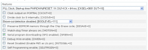
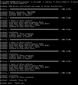
To use V-USB you need to change the fuse bits to enable the PLL with the internal oscillator. The bits read as: -U lfuse:w:0xe1:m -U hfuse:w:0xdf:m -U efuse:w:0xff:m
We’ll use the command prompt to upload the fuse bits to the ATtiny85, we could do it through the makefile if we wanted to.
Download the modified V-USB EasyLogger code here: ATtiny85_V-USB_Test_v1.0
Wire it up and plug it in
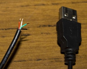
Find yourself a USB type A cable that you aren’t using any more, cut the wire and then solder it up to a 4 pin male header. You can add some glue to make sure the wires don’t move after soldering.
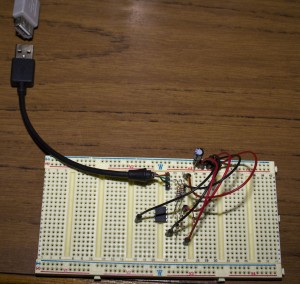
Now wire it up on the breadboard. (I mixed up D- or D+ a few times so triple check everything!). I’ve left the picture pretty large so you can easily see it all connected.
Plug and pray! 🙂
And that concludes my playing around with V-USB, it’s pretty exciting seeing your small MCU send some digits to your computer, think of all the possibilities we could use for it now.






Alex, this is really nice, and thank you for this research and tutorial. However, it would be much better if you manage to upgrade your temp logger for easier data acquisition. Just add a mini-usb port on board and modify the firmware in such a manner that it would printout the log into excel (notepad – whatever) when connected to the computer with subsequent resetting the log.
Heya, the upgrade is in the works, this tutorial was just my way of documenting my progress (although it didn’t mention the Standalone Temp Logger).
Here are the steps that I’ll do:
– Port and test the temp logger code over to WinAVR. I’m about half way through it.
– Integrate into V-USB code, demo it and post schematics/firmware but it will only run on 5V (unless of course you want to add a switch to choose 3V or 5V)
– Research and use some parts to be able to switch between 3V for logging and 5V for USB automatically (I’m thinking of using a small mosfet, lots of testing will need to be done to check for battery lift)
– Release the 3V-5V version schematics/code
– Make a PCB of it (probably will be 1.5-2x larger than before)
nice to learn this news 🙂
will you document the process of porting? (what’s the current IDE and what are the differences, btw?)
this increase in size actually doesn’t matter – it still remains small, and I hope, same power efficient).
think of adding a 6 pin header instead of a usual usb jack – you can use 4 pins for usb, and the rest (one or two) – sort of a jumper (when it’s closed – we use usb, when it’s open – we’re in a logging mode)
by the way, wanted to ask you – what could be the other ideas of use cases for such a usb device? (but for temperature sensing).
Yep I will document the process of porting the temp logger though it’s not hard to do for my code as it’s all pretty simple stuff. It’s just going from the Arduino IDE to the WinAVR IDE so we don’t use things like digitalWrite or pinMode anymore (but we could just write/copy these functions if we wanted to).
I was also thinking of just a pin header so then the size could remain the same and it would just be another board for the USB part which you plug in… though then you’d need to always carry around 2 boards and then it’s likely that one will probably end up be lost 😛
Other uses of the USB part, if you change the code you could perhaps have it log the temperature to the computer directly then use that data to make a website with up to date/live temperature. Maybe if it hits a certain temperature, your computer could email you or perform a certain task (that an AVR couldn’t easily do).
Another example could be to have multiple temperature loggers in different parts of the home,office or anywhere and make a master USB device to collect all the data and put that on your PC which could monitor all the temperatures. Maybe an early warning fire system if you have a lot of them.
Hi, great little tutorial. I’m a newbie coming from the Arduino world to the ATTiny chips, I managed to recreate this by uploading your .hex file using avrdude (using the arduino as the programer) and it worked first time. However, now i’m trying to play around with the main.c code and i’m having issues compiling the program using programmers notepad and even at the command line. I keep getting error 2’s – file not found. The first issue was due to a “gccversion” not found, I managed to fix this by removing reference in the makefile as it was under an eye-candy header! But this just led to another error 2 – file not found but this time involving main.o! I can’t see what i’m missing, can you help? Thanks,
Found it! For anyone else having similar issue I changed the line:
CC = /c/WinAVR-20100110/bin/avr-gcc
to
CC = c:/WinAVR-20100110/bin/avr-gcc
in #define programs and commands section and everything compiled correctly.
Hmm that’s very strange but thanks for bringing this up, I’ll update my makefiles for new projects I release to have it all as c:/ like you have done.
any ideas how to make a mains blackout logger out of this? right now I am in india, and this seems to be quite a problem over here – sometimes you come back home at the evening time and can’t understand why the room is stinking. Later you realize that the fridge got defrozen because of the power outage during the day, and you never know how long it lasted.
Hi, I have made a blackout detector found here – http://www.insidegadgets.com/projects/non-contact-blackout-detector/
The basics is that it just uses 1 pin for ADC to detect interference from an AC source like a outlet. If you modify the SATL, you would just need to take out the temperature components and use it for detecting interference.
Then I suppose you would need is to program the ATtiny with the current time or you could use a DS1307 RTC. You would write to the EEPROM when the power goes out and when it comes back on, then you can transfer that data to your computer via the USB.