Today we’ll introduce the N Channel Mosfet and show how we can use it to allow us to switch between voltage sources.

Mosfet explained and example
We can think of a mosfet sort of like a transistor, it has a gate, drain and source compared to the transistor which has base, common and emitter.

With transistors that we want to act as a simple switch it’s all about adjusting the current at the base however with mosfets it’s actually the voltage at the gate that turns them on. Because we don’t lose current when turning the mosfet on, this means that it’s actually more efficient than a transistor.

In datasheets you see it called Vgs and they provide you a minimum voltage that is needed before the mosfet will allow current to flow through the drain and the source.

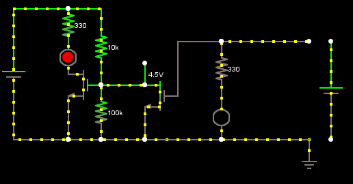
We can build a simple circuit using a mosfet, LED, 10K and 330 Ohm resistors and a 10K pot to show what happens at different gate voltages. The bottom resistor in the diagram is the 10K pot.

In my circuit I’ll be using a STP22NF03L that has a Vgs of 1V and the circuit runs on 5 volts. By using a 10K resistor and the 10K pot we create a voltage divider which will let us choose the voltage from 0V to 2.4V and we’ll feed into the gate of the mosfet.
Gate voltage (Vgs)     Current drain-source (Ids)
1v                     60nA
1.5v                   20uA
2v                     0.93mA
2.25v                  3.96mA
2.33v                  5.6mA
Above are the results that I observed.

So at 1V the LED isn’t on.

At 1.55V gate voltage the LED is barely on, amazing what 5V at 20uA can do!

Then at 2.3V the LED is very bright. So we have the relationship of a higher gate voltage allows more current to flow between the drain and source.
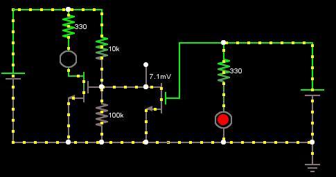
The change voltage source automatically circuit
How can a mosfet be used to change voltage sources automatically? I’ll show you.

By inserting the mosfet in such a way we are able to always have it on when our device is on battery 3V. Take note of the 10K resistor at on the left, it’s this resistor that connects to the mosfet gate which gives it 3V so it’s definitely turned on now. The diode on the left isn’t doing anything when we are running from 3V but do notice that there is another diode which is built into mosfet too.

We insert the 5V battery to simulate another voltage source. You’ll see that the 10K resistor on the left is still actually on however since both voltage sources grounds are separated this means the connection to ground is not through the mosfet so the resistor takes the full 5V voltage drop and the mosfet is now off. The circuit is complete by passing the 5V through the diode (pointing to the left) which also gives 0V at the mosfet. However notice that the mosfet’s internal diode actually allows the current to flow from the 5V to the 3V battery which actually means the 3V battery is being charged which is what we don’t want!

What we do is switch the mosfet’s drain and source around so that the internal diode faces the other way which restricts the current from flowing to the 3V battery. This simple circuit has taken me quite a few refinements to get to this working state but with the use of a circuit simulator it makes things easier!

Here’s the schematic. In my next post I’ll show how we use this in the Standalone Temperature Logger and changes to the code we need to make because if we run from the 3V battery we can’t run at 16.5MHz straight off the bat and we would only want to if the USB is connected.


hi there!
nice to see the movements!
the last two animations – what’s the difference in the left 10K side (on the first picture it remains still, on the second it moves a bit back and forward)
3v battery is to the right, isn’t it?
why doesn’t the current go through 330 resistor on the first of these two last animations?
common? is that common or collector?
Hi, thanks for watching the progress 🙂
1. In all cases the 10K resistor is always on, the animation was just wasn’t showing in the first one because 500uA is not much compared to the other currents.
2. Yep the 3V battery is on the right, it’s always connected.
3. The current does flow through the 330 resistor but again the animation doesn’t show it :/
To experience the animation better, you can load up the Circuit Tester with my project to see the circuit and check it out: Circuit Tester
I am trying to build a driver for driving 1 or more 1w LED using lm371 regulator, using 6v SMF battery. The drawback is very high heat dissipation from the regulator and the LED. Please provide me a mosfet circuit that will not dissipate so much of heat and also run more than one 1w LED in series / parallel.
Thanks on advance
Hi, this link should be able to help you out: http://www.instructables.com/id/Circuits-for-using-High-Power-LED-s/step6/The-new-stuff-Constant-Current-Source-1/
Thats a great tutor, I came to your blog while searching ‘using two powers sources to light led light but using one source a time until it is drained’. You got a really great explanation, visual effect make it more easier to understand.
Anyhow, I got a school project in hand. I need to create a circuit which will light led light by using two power sources (Solar panel 4v & batteries 3v). Could you explain your tutor by using these two power sources. I’m not that much good with circuits, so your help would be highly appreciated!
Thank you in advance.
Hi, please have a look at the how it works section on this page: http://www.insidegadgets.com/projects/automatic-voltage-switcher/
However if you are new to electronics, then I would suggest you learn about the components that make up this circuit – resistor, diode and mosfet.
how mos voltage source
Hi, I’m not sure I understand your question?
Hi,
I am 14 yeas old and I need this sort of circuit for one of my science inventions.
What I have is 2 voltage sources ( A and B) where source A is constant and source B turns on and off ( voltage from solar panel).
Basically, what I need is a circuit where when I provide voltage from source B, it should shut off voltage from source A and release source B and when B stops providing voltage, it should again switch to source A.
I was adviced to use a mosfet here. I was eyeing your automatic voltage toggle circuit.
Could you please help me and if you had some spare time, give me a detailed part list.
Thanks a Lot
Rochan
Hi Rochan,
This circuit may be a bit over complicated because my requirements were that source A didn’t have the diode voltage drop.
If your circuit is fine with the diode voltage drop (which I’m assuming it would be) then you can just do something like: http://www.insidegadgets.com/wp-content/uploads/2013/11/twovolt.png (the switch represents the side you plug / unplug)
All you need is a diode (can be any kind, like 1N4004G), the left battery is the lower voltage and the right battery is the higher battery. The diode is there to protect the left battery from being charged by the right battery.
hi
i want to make a circuit which switches the supply from battery 1 to battery 2, when the battery 1 is discharged and the same shld be charging while the system uses battery 2 and then vice versa.
also need to show the battery level (5 level) using leds.
hi,
I have a project to light an led set with solar panel and ac/dc adapter. if the solar panel voltage drops or not enough current to switch the led the curcuit will turn on the ac/dc adapter to feed the led.
thanks
Hi, this circuit would only cover voltage drops. For current measurement you’ll need a shunt resistors with IC or similar to monitor the current.
Hi,
Thanks for reply.
Could you help me to build a circuit for Two power sources( solar as a primary and wall adapter as a secondary power source).
when the voltage drops in the solar pannel the wall adapter will come into play.
Thanks for cooperation.
The simplest way would be to use the wall adapter voltage you want the solar panel to be above say 12V. Have a diode on the power supply to your load and another diode on the solar panel to the same load. If the solar panel is above 12V then your load will be powered by the solar panel.
Dear sir
I am using two dc supply and mosfet in between dc supply. -ve terminal of dc source connected with source of mosfet and +ve terminal of 2nd source connected with drain of mosfet
I’m on the hunt for a cuircuit to maximise the energy from solar panels. On my 1936 steel barge I have 6 x 230 watt panels seried in pairs to 3 epsolar controller then to an 12 volt 840 amp hour battery bank. In good wheather battries are fully charged by 10 o’clock. I’ve got two inverters, my thought is to use the surplus power to heat water. Therefore it would seem logical to have a switch cuircuit that monitors the battery bank, on reaching 14.4 volts it would switch the input to the second inverter heating water, when the battery bank voltage drops then the current is reverted to the batteries.
I hope you will find this an interesting problem and I look forward and thank you in anticipation of an reply.
Hi Beetle,
To keep things simple you could use an opamp like the LM358 to do the voltage comparison and then use 2x relay to switch between 1 inverter and the other (and use a not-gate for 1 relay) so it only switch on 1 relay at a time.
I have 12V 40 amp battery, 10K ohm pot and a dc motor so for controlling its speed which mosfet should i use
I am looking for a circuit design where I have two sources. Both are DC. One is coming from a regulated power supply and the other is a 12 volt battery. I want the power supply to have priority and also charge the 12 volt battery. When AC power is no longer present I would like the battery to supply power. Any help would be greatly appreciated. Thank you very much. Btw the current for all this is about two amps drawn from either source.
If it’s a 12V seal lead acid or car battery, you can just stick an LM317T with heatsink or a DC-DC converter to float the battery on 13.5-13.8V, once power is loss, it runs off the battery, kind of like a UPS, the downside is the DC power supply needs to be 15V or higher.
Hi,
How would I design a circuit that does the following:
Uses voltage source “A” to keep a green LED always on, except when voltage is sent to a red LED from voltage source “B”. I pretty much want to make an inverter with two power sources, without using a inverter chip.
Thanks in advance.
Hi Michael,
You can use an N mosfet with a resistor divider and then another N mosfet to pull the gate low of the first mosfet when the right battery is applied.
Battery 1 connected, Battery 2 disconnected
Battery 1 connected, Battery 2 connected
I would like to build a battery backup with power mosfets. I have a good supply of used N- channel from discarded battery inverters. will this circuit work with multiple mosfets in parallel for 25 A full current draw . I have experience in electronics but have never worked with power mosfet circuits. Thank you for your work to help everyone.
This looks very close to what I am looking for.
I have two 12V Li-Ion batteries charged to 13.5 volts running an instrument panel in a sailplane. The panel has computers, several gps/data loggers. We use the log to validate flight claims. Losing power renders the log as worthless.
Being Li-Ion, the primary battery will output 12 volts until the last second and gives no warning of the power failure until after it has happened.
I am looking for a low drain circuit that will automatically switch to the backup battery lets say when the primary drops to 10 volts. I start getting voltage warnings at this level.
Any guidance would be appreciated.
An image of a like glider can be seen at:
https://www.flickr.com/photos/batenburgl/5626690279
Hi Dan,
The easiest and quickest solution would be to connect each battery to the load with a diode in series (and make sure they are rated with a low voltage drop for the current you need), so essentially they would share the load but would mean that the backup battery would be used too.
Alternatively the solution you are after requires an op-amp like an LM358 (that can output 12V+), 2x N mosfets, 2x P mosfets, (forms a inverter) some resistors and 2x diodes. By adjusting the resistors on the op-amp you can set the primary battery cut off voltage but it also affects the cut in voltage (when it switches back to the primary battery), here’s a simulation – http://tinyurl.com/j5chago
Because the two resistors are dependent on the backup battery voltage, I would go for a voltage reference instead because the cut in and cut out voltage also depends on backup battery voltage.
And another way would be to use the 2x P mosfets with 2 diodes (they are used so one battery won’t recharge the other) and use a microcontroller to detect the voltage though a resistor divider and have that switch which battery to do using the LM358 op-amp as a high voltage buffer.
Hello,
I have 5V USB Supply and , 4 AA batteries(1.5VX4=6V), which is step down to 5V. so I have both supply voltages on same level. How could I switch from battery to USB and USB to battery automatically ? my Priority Supply is USB and if USB is removed , system will work on Batteries.
what changes should be made to above circuit?
Hi Taher,
If you aren’t drawing too much current and aren’t too concerned about a little voltage drop, the easiest way would be to use a schottky diodes on the positive side of each supply right when it connects to the circuit and join the other end of the diodes together.
@Alex:
I want to run a Seven Segment Digital Clock on USB Power supply but if there is not USB supply connected then system should run on 4 AA batteries. Current consumption is around 500mA-8008mA. schottky Diode is not able to provide efficient Current. Kindly Help me with another proper solution.
Another way would be to use 4x P mosfets, 2 per power supply, back to back, gates joined together. One gate goes to the power supply. Then you use a NAND gate and connect the inputs to that gate and the battery positive, the output will go to the other 2x P mosfets gates.
This will give a circuit that works if the power supply and battery is connected or only if the battery is connected. It won’t work if only the power supply is connected.
The easy/less component count way – grab a small/cheap 6/8 pin MCU, hook up the 2 P mosfets to the outputs and 2 pins to detect each voltage, then just switch the P mosfet on or off depending on the voltage state.
Like this: https://www.insidegadgets.com/wp-content/uploads/2017/06/nand-2-p-fet.png
what about this circuit?
https://i.stack.imgur.com/YFqhV.gif
Yes that would work but once again you have the diodes dropping a little voltage, the mosfet is only there to switch the supply but even if you didn’t have it, the diodes protect the main supply and battery from each other. You can buy schottky diode that are rated for 5A/10A, etc, without too much of a voltage drop, say 0.4V.
I had a circuitry that change 3 voltage. that is 6.0v – 8.5v – 4.2v.
however, the 8.5v drop to 8.0v before swiching to 4.2v. any suggestion?
Hi Irwin, in this case, it might be best to use a MCU’s ADC to monitor the power rails (with resistor dividers) and then to control mosfets to determine which voltage should be applied to the load. You just need to be careful on how you switch the mosfets and how the circuit starts up (as MCU will take a few milliseconds to startup).
Hi Alex,
Your voltage switcher, could it be used with say 4 AA batteries in series as backup voltage and a mains power 6v source that works continually until a power outage forces a switch to the plain penlight batteries.
Are the resistors still the same ? If not how did you calculate therm ?
Is VCC the positive terminal of the load being powered and are the separate grounds simply the negative terminals of each source ?
Thanks in advance.
Hi Rod,
Yes you can use the same resistors for the mosfet as I did. The 330 ohm resistor/LED is just acting as a load to test how it looked. Yes the grounds for each power source are different, if you would prefer you can use this one instead: https://www.insidegadgets.com/wp-content/uploads/2020/06/vcc-switching.png.
But if you don’t mind having a voltage drop for the 4 AAs, then you can just simply use the 2 diodes method which is easier:
Battery > Diode > VCC
4xAA > Diode > VCC
Hi Alex,
Your voltage switcher, could it be used with say 4 AA batteries in series as backup voltage and a mains power 6v source that works continually until a power outage forces a switch to the plain penlight batteries.
Are the resistors still the same ? If not how did you calculate therm ?
Is VCC the positive terminal of the load being powered and are the separate grounds simply the negative terminals of each source ?
Thanks in advance.
Ok Alex,
So as long as the voltage supplied to the gate is above 1volt then the batteries aren’t connected and if the gate voltage falls then the batteries kick in as backup, is that right ?
Also..
A voltage drop is not recommended by the device manufacturers.. it’s a cat door with sensor.(use alkaline not rechargables they say)
So are the D1 and D2 diodes on your 2920/06 switching circuit the same ? They’re just standard not zener then..
And is the LiPo terminal just the gnd of the batteries ?
The source will be 6v instead of 5v I presume that’s fine.
Thx
Rod
If they don’t recommend a voltage drop, then these circuits won’t be suitable as in the examples, there is a diode dropping the 5V to 4.3V or so in my example and my load was only 100-300mA.
The best solution would be to use an “idea” or “perfect” diode chip, maybe something like the LTC4353 if you require a few amps or the NLAS4157 if you just need 100-300mA.
Hi
Hope you can help
I am trying to build a circuit (which I think should work with a transistor and a relay), its job will be as follows
It must monitor 2 sets of batteries (A & B) , while A or B is in use, as soon as it (A or B)(the one in use) drops by 1.5v, the circuit must automatically change to battery B and or A and then also simeltaneously charge Either of the Depleted batteries to it’s full potential !
I am using 4 Laptop batteries in two banks of 7.4 v each.
This circuit must run a Motor (4-5v)
Thanks in advance