Just a quick simple project I’ve been meaning to do which is to have a nRF24 Wifi module connected to my 12V battery that’s charged by a solar panel and is running the siren of my alarm system. The nRF reader module will connect via USB to the PC and we’ll output the voltage to a file so we can parse the file anyway we like.
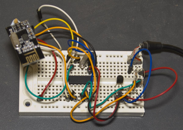
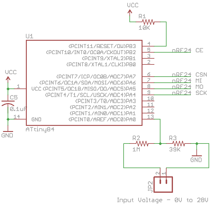
For the TX side, we use an ATtiny84 and as we’ve seen before, we use an analog voltage reference of 1.1V and I’ll use a 1M / 39K resistor divider which allows us to measure up to 28V (not that I expect it to go that high). We’ll send the voltage once a second.
// Read the voltage
sbi(ADCSRA, ADEN); // Turn on ADC
analog_read(adcPin); // First reading is ignored
_delay_ms(1);
int adcValue = analog_read(adcPin); // Read ADC
cbi(ADCSRA, ADEN); // Turn off ADC

// Split up ADC result into 2 bytes
data_out[0] = (adcValue >> 8);
data_out[1] = (adcValue & 0xFF);

// Power up the nRF24L01 and transmit the result
TX_POWERUP;
_delay_ms(3);
mirf_transmit_data();

// Power down the nRF24L01
POWERDOWN;

// Watchdog sleep for 1 second
watchdog_sleep(T1S);
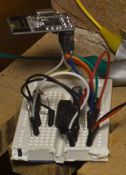
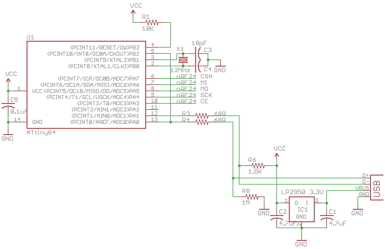
For the RX side, again we use an ATtiny84 and use V-USB to transfer the data received to the PC. If no data is received, we’ll send a “.” dot to let the PC know we’re still communicating to it.
USB_PUBLIC uchar usbFunctionSetup(uchar data[8]) {
 ...
    if (data_received == true) {
      // Read data and multiply (1M / 39K resistor divider), you can change depending on your actual resistor values
      double calculateDouble = (double) ((double) ((data_in[0] << 8) | data_in[1]) * 1.074) * 0.026614;
}
...

while (1) {
  if (data_received == false) {
    if (mirf_status() & (1<<RX_DR)) {
      mirf_CE_lo; // Stop listening

      data_in[0] = 0; // Clear the data_in
      data_in[1] = 0;

      mirf_CSN_lo; // Pull down chip select
      spi_transfer(R_RX_PAYLOAD); // Send cmd to read rx payload
      spi_read_data(data_in, mirf_PAYLOAD); // Read payload
      mirf_CSN_hi; // Pull up chip select
      mirf_config_register(STATUS,(1<<RX_DR)); // Reset status register

      data_received = true;
      RX_POWERUP;
      mirf_flush_rx_tx(); // Flush TX/RX
      mirf_CE_hi; // Start listening
    }
  }
  usbPoll();
}
On the PC side, we just the output from V-USB, I did find that you shouldn’t use nBytes to break out of the loop like I used to because after a few hours, the receiver would drop out.
nBytes = 1;
while (1) {
  nBytes = usb_control_msg(handle,
  USB_TYPE_VENDOR | USB_RECIP_DEVICE | USB_ENDPOINT_IN,
  USB_TRANSFER, 0, 0, (char *)buffer, sizeof(buffer), 5000);

  if (nBytes > 0) {
    if (strcmp(buffer, ".") != 0) {
      printf("%s\n", buffer);
      fwrite(buffer, 1, strlen(buffer), pFile);
      fwrite(newline, 1, strlen(newline), pFile);
      fflush (pFile);
    }
...
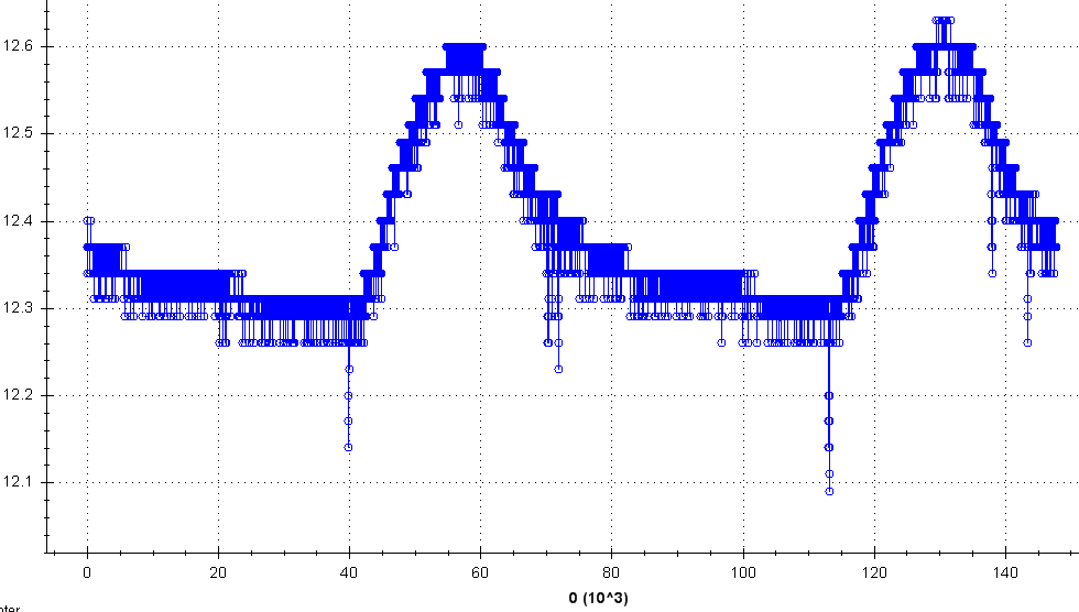
It’s all working well after 2 days. Download nRF24_Voltage_Sensor_v0.1
Here’s the graph of our results after 2 days (I used DatPlot to generate this graph) –


[…] http://www.insidegadgets.com/2013/08/08/nrf24-wifi-voltage-sensor/ […]