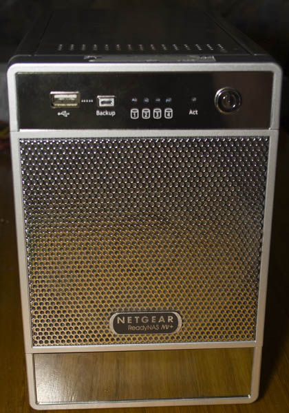
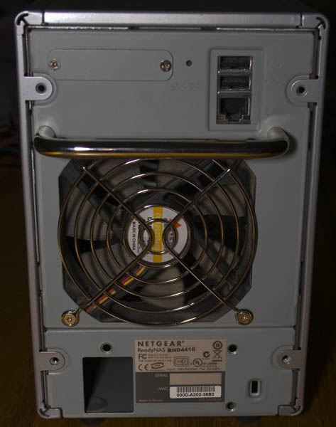
Today we’ll be taking a look at the Netgear ReadyNAS NV RND4410 NAS (version 1) which was released back in 2007, has 4 drive bays, front LCD, gigabit ethernet and 3 USB ports. This particular unit wouldn’t power on anymore.
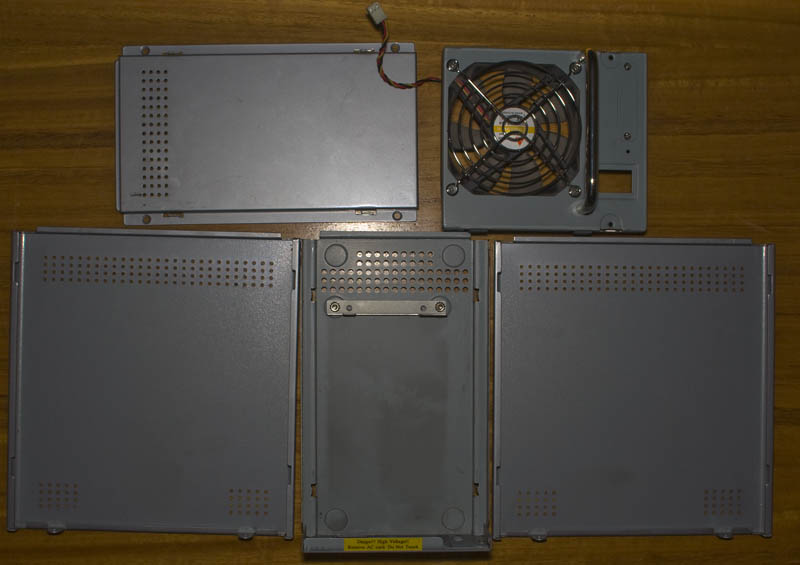
Quite a bit of screws later and we’re in.
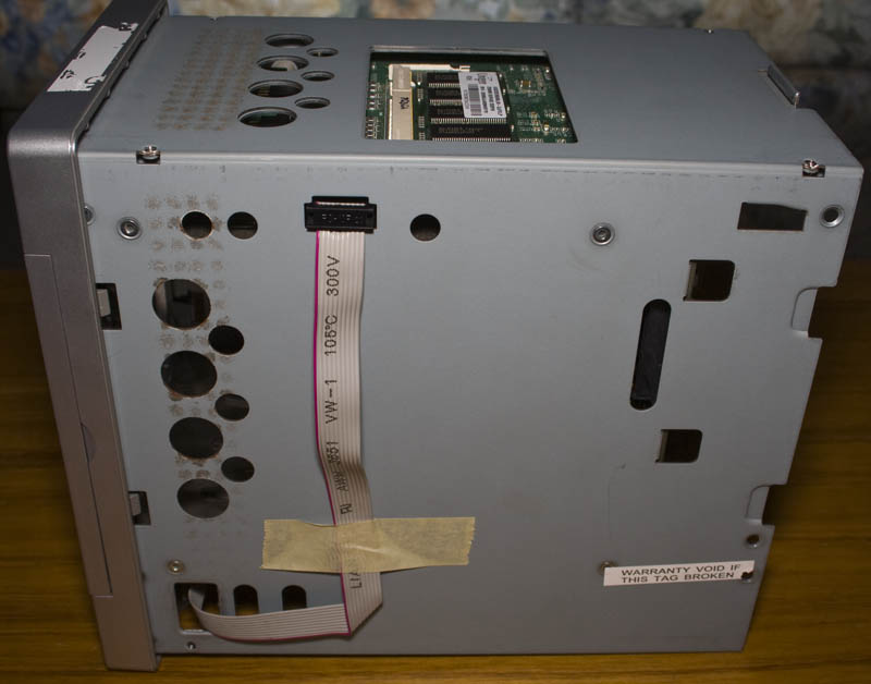
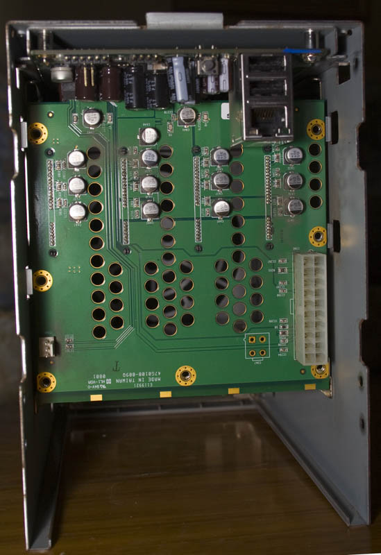
It’s a fairly modular design (I took the power supply out beforehand). We have the LCD connector running up to the top of the case, the memory module up top. The backplane has a standard ATX power connector has PCI connector to connect it to the main board; the main board can easily slide out.
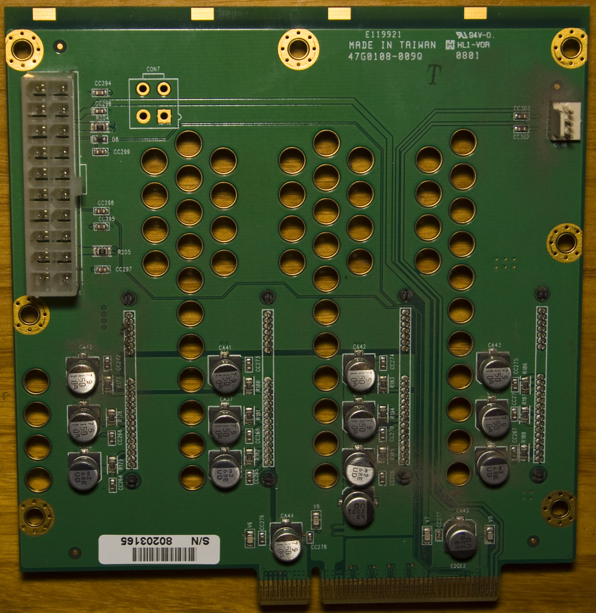
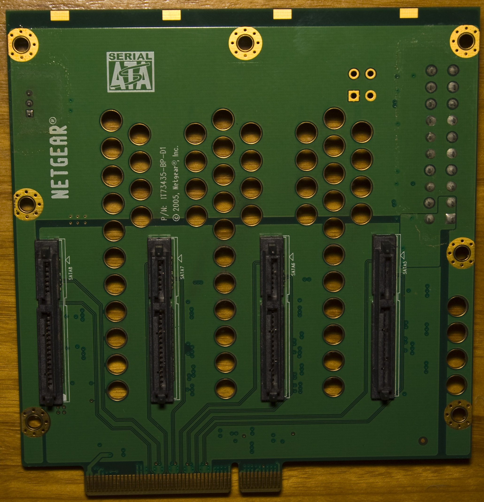
A close up of the SATA drive blackplane. Even though it has a standard ATX connector, you shouldn’t plug in an ATX power supply (which I mistakenly did), you have to remove the -5V and -12V rails as shown in this PDF: ReadyNAS_PSU_pinout.
.
Main board – top
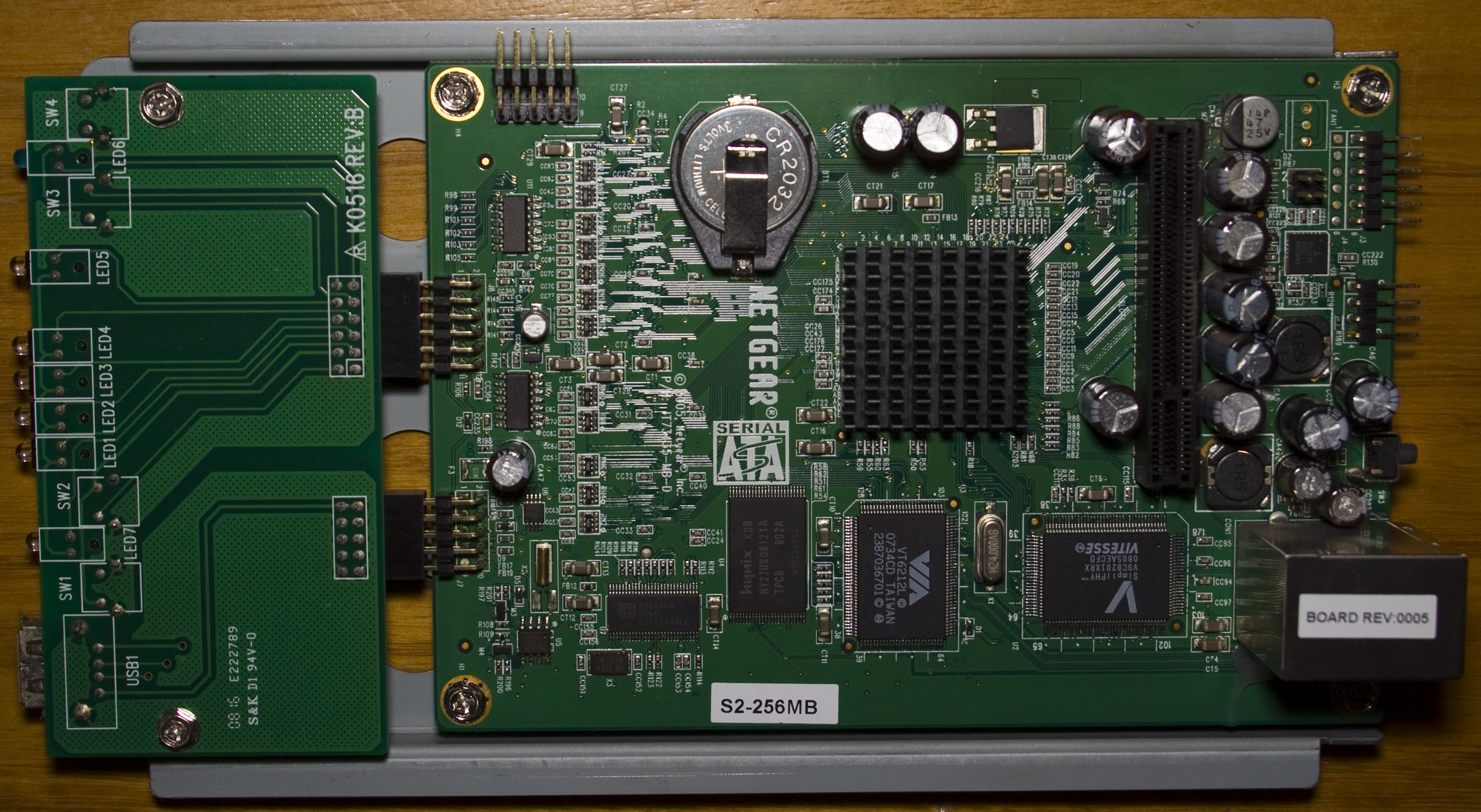
Now for the main board, we have have a board on the left which has the LEDs, buttons and a USB connector on it. The top connector is used for the LCD module and we’ve got a CR2032 battery for the RTC.
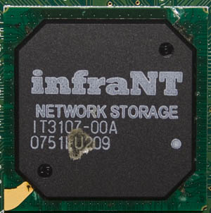
Infrant Technologies Processor
The main processor is a 32bit RISC with 4 SATA channels, DDR RAM interface, hardware raid 0/1/5. Since it’s built in hardware raid and assuming they are using this, if the unit did fail you’d have to by another one to recover your data.
IT3107-00A, IT3107_Brochure
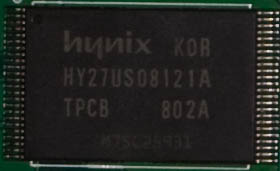
Hynix 512Mbit NAND Flash
HY27US08121A
Unknown chip
I’m guessing this is some of the memory, probably 64Mbit or 128Mbit
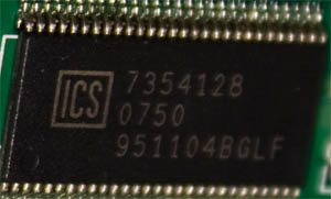
7354128 951104BGLF
ICS Programmable Timing Control Hub
Used to generate and distribute clocks to the different components on the board. Capable to provide clocks to CPU, DDR, PCI and AGP ports.
951104
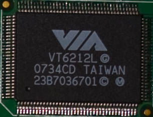
VIA 4-Port USB 2.0 Controller
VT6212L
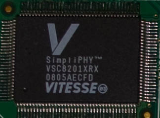
Vitesse SimpliPHY Gigabit Ethernet Controller
VSC8201XRX
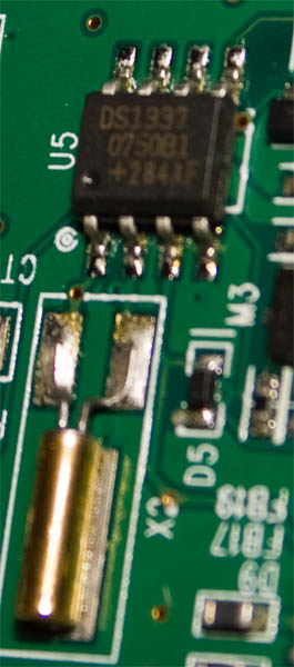
Maxim RTC
One of the most common RTC
DS1337
.
Main board – bottom
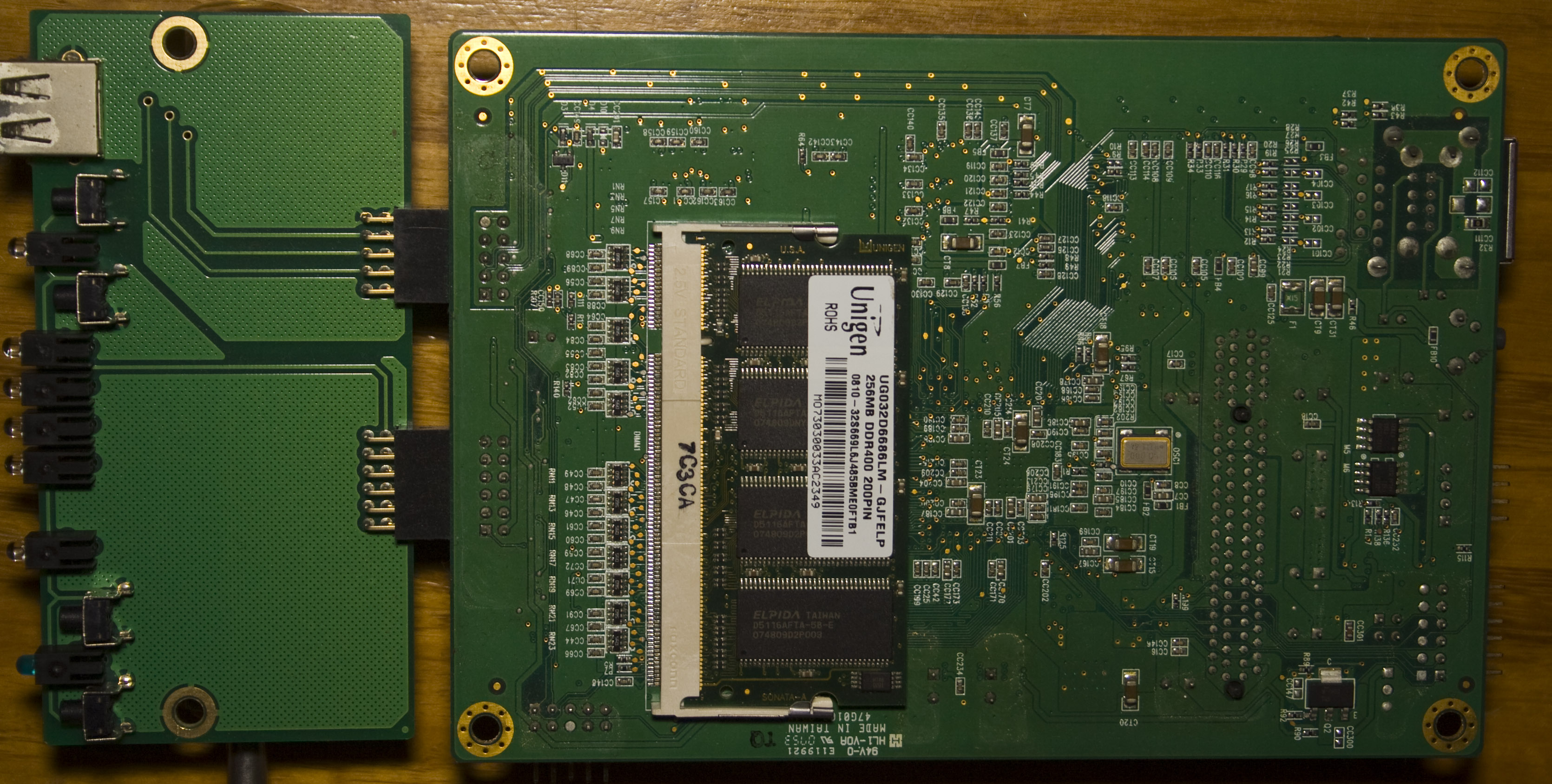
Not much on the bottom side of the board, just the 256MB DDR400.
.
LCD Controller
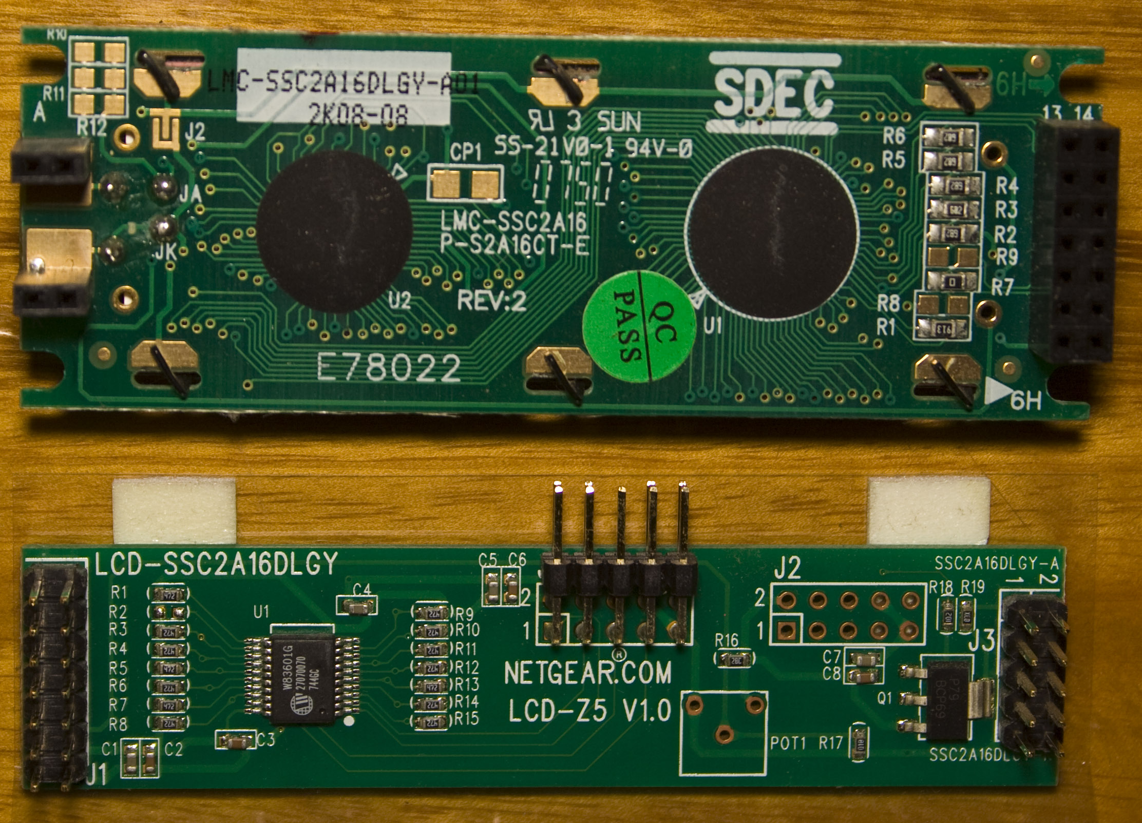
SDEC LCD Screen
SSC2A16DLGY
Nuvoton GPIO Expander
Allows us to use I2C to interface to the LCD
W83601G
.
Power Supply
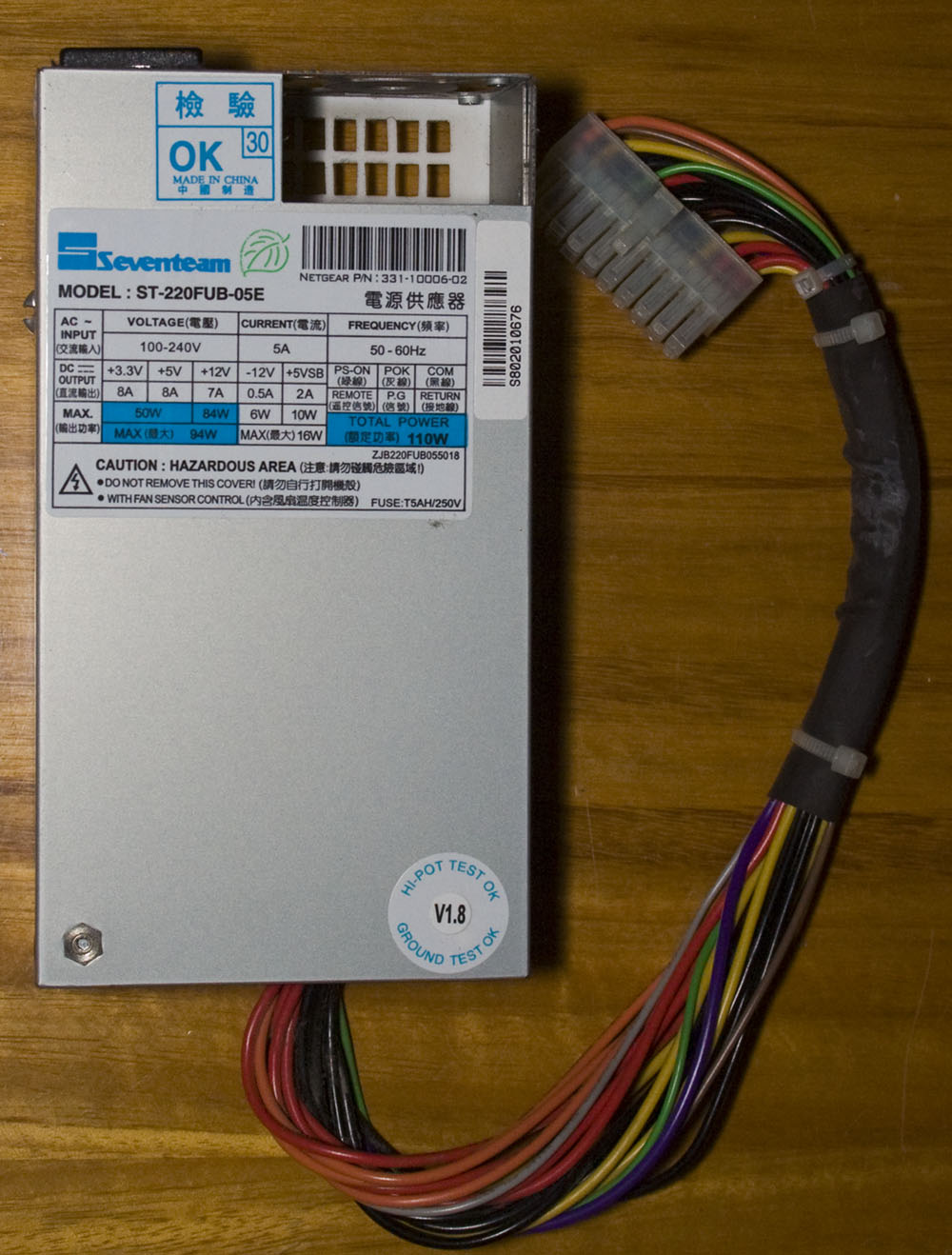
We’ve got a Seventeam 110W ST-220FUB-05E which has had it’s fan removed.
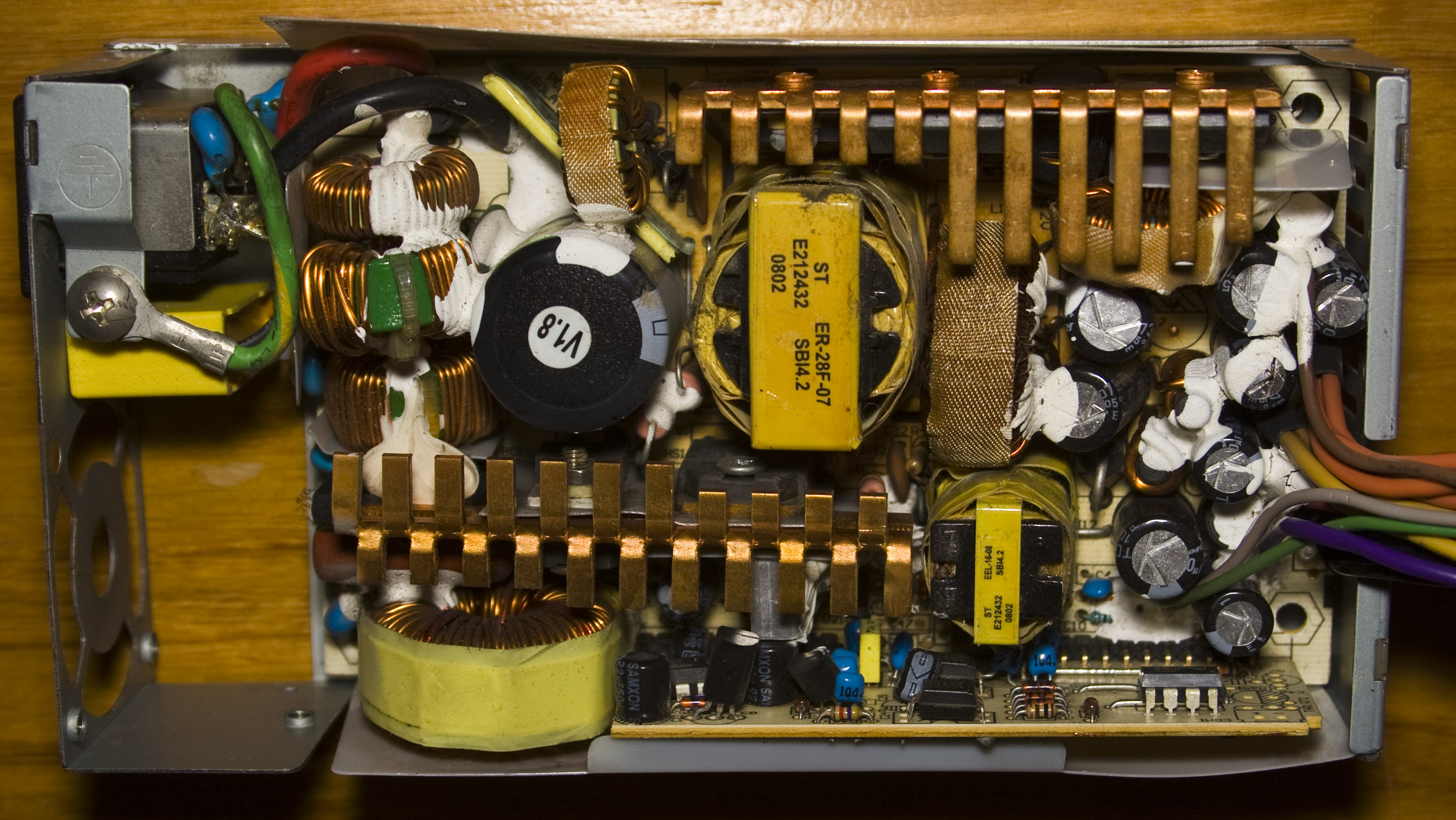
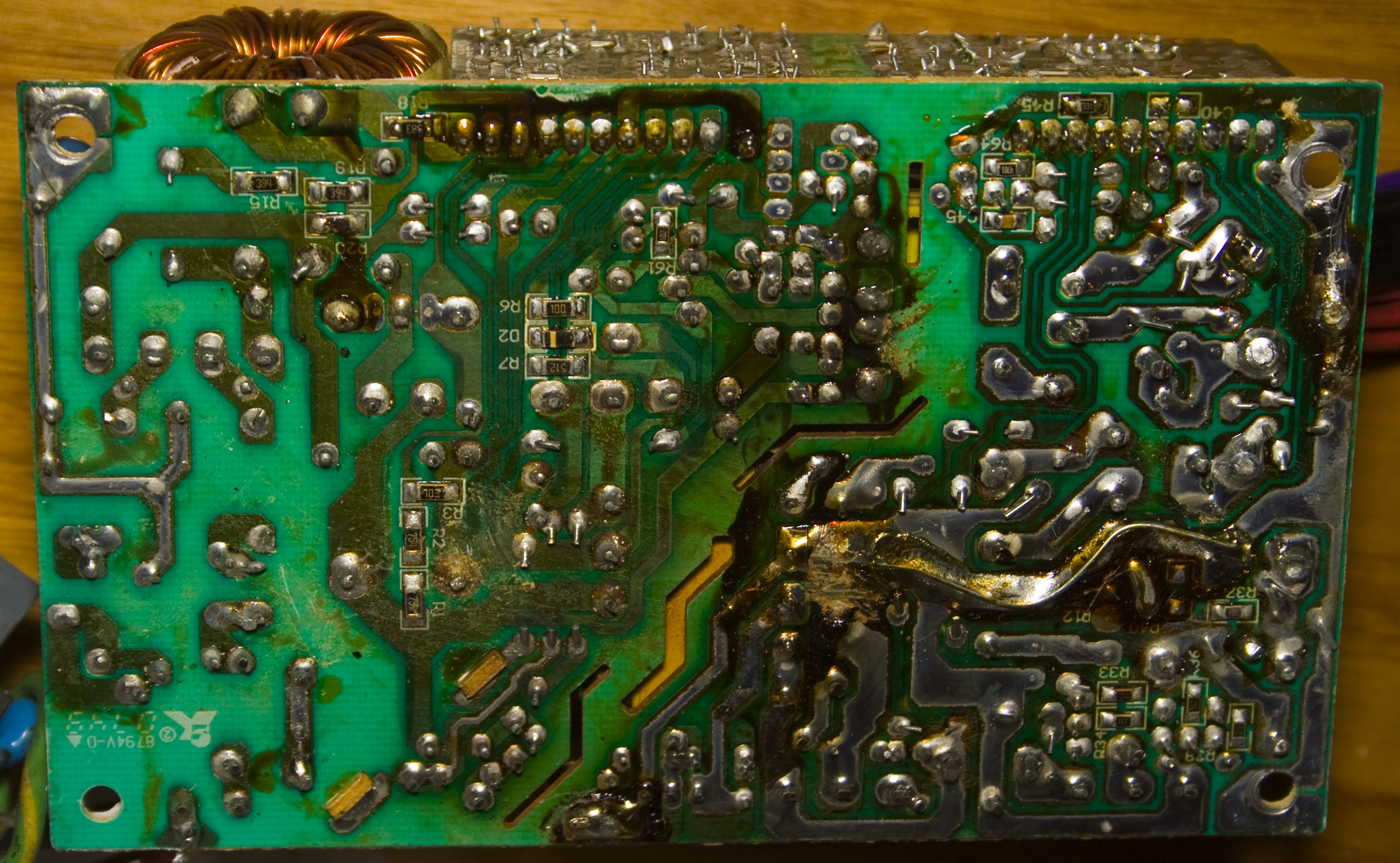
Looks pretty standard, there is 1 capacitor that needs to be replaced and this power supply is faulty. Bottom of the board doesn’t look pretty.
I’m thinking about re-using the case, adding in a Raspberry Pi with 4x SATA drives connected via USB and seeing how Raid5 using mdadm performs over the network, I’m guessing under 5 MB/s. As long as it works, it will put good use to my Pi, I should be able to have the lights and LCD working too which will make it look nice!


The ICS chip is a clock generator, 951104.
http://tec.icbuy.com/uploads/2011/5/6/951104.pdf
It handles the CPU/DDR/etc clocks for the whole system.
Thanks Duo
I have required power supply my phone number 9654485052
Besides the flux on the bottom of the PSU, it looks as if some of the solder has crystallized, and needs to be re-heated. When the solder crystallizes, the junction it forms becomes intermittent or has a high resistance. A quick re-melt cures the problem.
Keep us informed if you finally do this hack.
Thanks
Yep it’s been done – http://www.insidegadgets.com/2014/03/29/building-nas4pi-a-nas-built-using-the-raspberry-pi-part-2/
Hello,
my Seventeam 110W ST-220FUB-05E has 3 SMD burned and all capacitors must be replaced 🙁
Thanks to your “back board” photo I can see that we have 2 resistances R6 (10 Ohm) and R7 (5.1 kOhm), but I need to know the code of diode D2.
Can you help me please?
Thank you
Hi Giro, I don’t think the diode has any codes on it, I would try replacing it with a high voltage rated (to be on the safe side) possibly rated at 3-5A.
Hi,
Thanks for posting this. I just had an older ReadyNAS NV PS blow and it looks like the Seventeam will work as a replacement. I am somewhat handy, but I do not have a deep grasp of power supplies. Can you elaborate on what “you have to remove the -5V and -12V rails” means? The PDF suggests that some pins need to be re-wired, but “remove” sounds like I would just have to cut the wires. I assume the stock PS from Seventeam cannot be used un-modified in an NV or NV+.
Insight appreciated.
Thanks,
Greg
Hi Greg,
I believe that the extra 12V rails they added were all tied together so you should cut the -5V or -12V rails and then it’s up to you if you wish to hook up the extra 12V rails to the existing 12V rail, chances are it should work just fine without the re-wiring.
Greg Tarsa, did you order the stock Seventeam ST-220FUB-05E? Did it work without modification?
seventeam model: st-220fub-05e
require Seventeam ST-220FUB-05E.
please guide us
I hope everyone will forgive me for awakening this thread, but also that someone will respond to it. I have an NV+ that has just been certified dead (I’ve tested it with a modified ATX power supply and it won’t start) and I want to try to use the enclosure and the backplane to make a DIY NAS using a Wandboard Quad running Arch Linux and open-source NAS software. (The Quad, unlike the Raspberry Pi, has a SATA connector.) If anyone has suggestions and/or knows of anybody who has done this, please let me know.
TIA
Les