On Mothers day, I had this idea that it would be fun to make a little LED heart to light up with various animations and would be powered from a coin cell. The board would just be about the same size as the coin holder.
(sneak peak of the end result)
The first step was choosing the MCU, we could go with an ATtiny84 and have an LED on each pin but it’s fairly big, an ATtiny25 with shift registers would work but that would take up most of the board. We can use a technique in which you could configure a series of LEDs in such a way that you only need a few pins to control more than double the LEDs when you reach 4 pins – it’s called charlieplexing.
By configuring both ports as outputs and having one source current and the other one sink current we can effectively control both LEDs depending on which port does what. To calculate how many LEDs an number of pins can control you can use the formula (n2)-n, so for 4 pins we could control 12 LEDs. When you have 3 or more pins, you need to tri-state the pins that aren’t been used otherwise you may have the wrong LEDs light up.
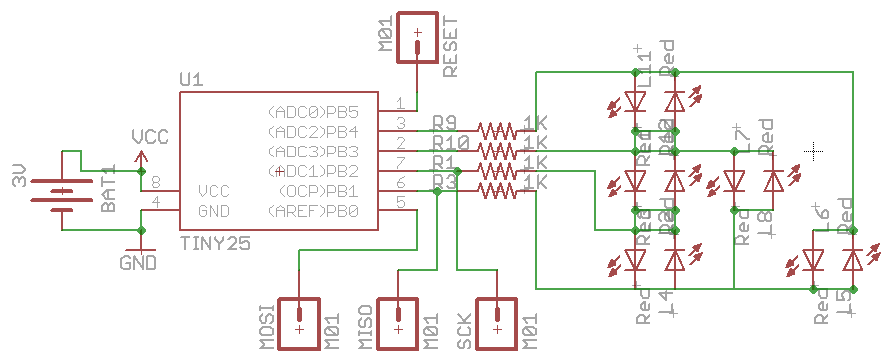
I only need 10 LEDs and I have 1K resistors on each pin to limit the current but also to provide short circuit protection in case an LED fails or we short two pins together accidentally. One problem with charlieplexing like any other LED displays is that you’ll need to refresh the LEDs many times per second however it’s easily achievable.
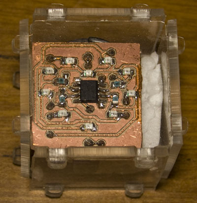
I built the hardware all up on a PCB and had an acrylic cube already made when I was testing my CNC machine and it all fits together well. Now for the code.
// Combination of source and sink ports in arrays
uint8_t ledStandard[] = {PB3, PB1, PB3, PB4, PB4, PB3, PB3, PB2, PB2, PB3, PB1, PB4, PB1, PB3, PB2, PB1, PB4, PB1, PB1, PB2};
uint8_t leddualArray[] = {PB3, PB1, PB3, PB4, PB1, PB2, PB4, PB3, PB4, PB1, PB3, PB2, PB2, PB1, PB2, PB3, PB1, PB3, PB1, PB4};
uint8_t ledsActive[] = {0, 0, 0, 0, 0, 0, 0, 0, 0, 0}; // Which LEDs should be lit
volatile uint8_t timeOver = false;
Firstly we have our variables, the first two have the source/sink ports so we can loop through the array and easily switch on the LEDs. The ledsActive are used to tell some of our functions which LEDs are on and then we can easily modify that array to switch them on or off.
// Configure two ports as source and sink to light up the LED
void light_up(uint8_t portSource, uint8_t portSink) {
	DDRB |= (1<<portSource); // Setup
	DDRB |= (1<<portSink);
	PORTB &= ~(1<<portSink);

	PORTB |= (1<<portSource); // Switch on
	_delay_ms(1);
	PORTB &= ~(1<<portSource); // Switch off
	_delay_ms(1);

	DDRB &= ~(1<<portSource); // Back to tri-state
	DDRB &= ~(1<<portSink);
}
The way we switch on each LED is setting the two pins as outputs, switching the source port on and off and then setting both back to tri-state.
// Light up the LED array for 262ms
void timed_light_up(uint8_t ledArray[]) {
    TCNT0 = 0; // Reset counter
    TCCR0B = ((1<<CS02) | (1<<CS00)); // Start timer at 1024 prescaler

    while (timeOver == false) {
        for (uint8_t x = 0; x < 10; x++) {
            if (ledsActive[x] == 1) {
                light_up(ledArray[(x*2)], ledArray[(x*2)+1]);
            }
        }
    }

    TCCR0B = 0;
    timeOver = false;
}
Next we just have our timer count to until it overflows which is 262ms at 1024 prescaler and constantly loop through all LEDs and only turn on those that need to be lit.
// Tri-state ports
DDRB &= ~((1<<PB4) | (1<<PB3) | (1<<PB2) | (1<<PB1));
PORTB &= ~((1<<PB4) | (1<<PB3) | (1<<PB2) | (1<<PB1));

// Turn on Timer0 overflow interrupt
sbi(TIMSK, TOIE0);
sei();

while (1) {
	for (uint8_t z = 0; z < 10; z++) {
		ledsActive[z] = 0;
	}
	for (uint8_t z = 0; z <= 10; z++) {
		timed_light_up(ledStandard);
		ledsActive[z] = 1;
	}
We have our first animation which lights up each LED one at a time, there are other animations which I haven’t listed above.
Download ATtiny25_Heart_LED_v1.0
As per the video, it all seems to run good off a 3V coin cell, it’s a little dit in daylight however swapping out the 1K resistors to 220 ohms would help. At the moment, we’re only drawing about 1mA so potentially off a new 3V coin cell it could last about a week. We could extend the runtime if we added some a couple seconds between each animation.


