I’ve been looking to upgrade the way that I have been sending SMS’s which is through a Nokia phone using F-Bus and came across the SIM900A module. If you can spare the cash, I would recommend it over Nokia F-bus as it’s easier to use.
It’s a relatively cheap module for $20 on Ebay but you need to check that the SIM900A works in your country before buying it. By using AT commands, we can send and receive SMS quite easily and I was going to cover this but there are already tutorials around that cover it quite well.
So instead I’ll be explaining how we can use the SIM900A’s GPRS to fetch a file from a webpage and print it out so we can process the data. Potentially you could use this instead of waiting to receive an SMS, for greater data transfer rates vs price per SMS or better yet for control of a device such as a remote control car/quadcopter as long as you have mobile reception.
SIM900A Hardware
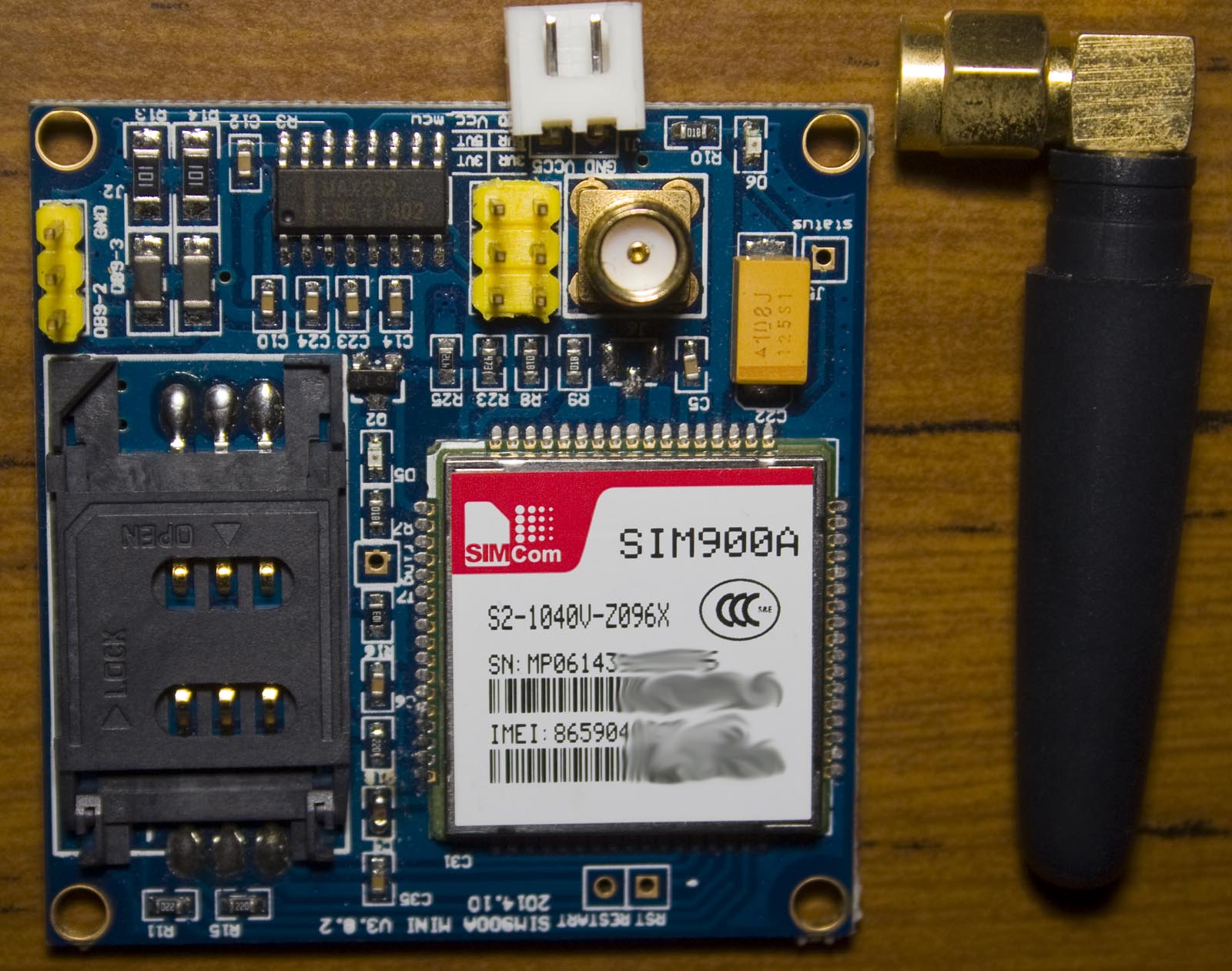
The one I bought is the “SIM900A Mini V3.0.2, 2014.10” which comes with an external antenna. The PCB has a MAX232 on board if you wish to hook it up to your computer directly.
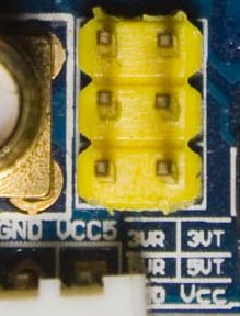
In my version, I have a header which has 3VR and 5VR(receive), 3VT and 5VT (transmit), VCC and GND; we’ll just be using the SIM900A’s outputs directly so I will use 3VR and 3VT.
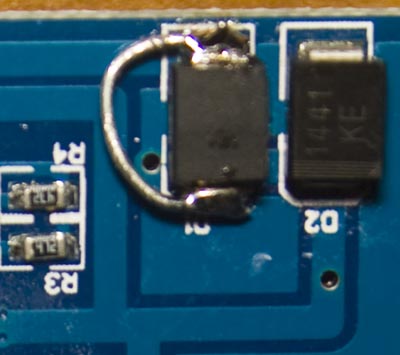
The power connector has VCC5 labelled and it accepts 3.5V to 5V input. I found when powering it from a Lipo battery, when you insert your SIM card and power it on, it will try to connect to the mobile provider but then it resets itself because the voltage gets too low. I had to bypass one of the input protection diodes connected to VCC with a small wire to remove voltage drop and now it works without issues.
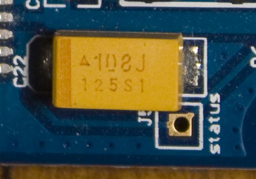
We’ve also got what looks to be a 100uF 6.3V tantalum capacitor on the main power rail which if it was really running at 5V is getting fairly close to the tantalum’s rated voltage. The industry standard says to use a tantalum that is double your voltage, otherwise you might have problems down the track (e.g it blows up). Our 4.2V Lipo is a small risk that I don’t want to take and since it’s only 100uF I might replace it with a 220-330uF 16V electrolytic cap later on or use a higher rated tantalum.
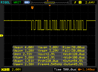
Initially I connected it up to our Arduino by wiring SIM900A 3VT (Tx) to Arduino pin 0 (Rx) and Arduino pin 1 (Tx) through a 2x 330 ohm voltage divider to SIM900a 3VR (Rx) however I wasn’t receiving any data. After probing, I found that it seems like the MAX232 on the Arduino is leaving the bus high which is resulting in an increased 1.28V offset on the Arduino Rx (pin 0).
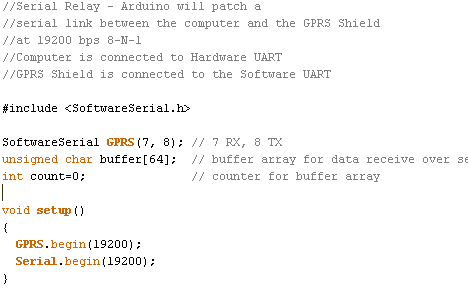
The solution to the above problem is to use Arduino SoftSerial (example /softserial_read) on a different set of pins so the SIM900A will communicate through the software serial and the Arduino will forward it to the serial window and vice versa. We connect the 3VT (SIM900A Tx) to pin 7 and 3VR (SIM900A Rx) to pin 8 and set the baud rates to 19200. From now on, this is how I’ll always use serial interfaces on the Arduino instead of patching into pin 1/0. The SIM900A supports auto baudrate detection too and you can also set it to be a static baudrate if needed.
Communication between SIM900A and using GPRS to fetch a webpage
RDY
+CFUN: 1
+CPIN: READY
Call Ready
When plugging in the power, the SIM900A response with the above. In-between commands that we receive, there are squares that progressively appear on the serial monitor.
AT+CPIN?
+CPIN: READY

AT+CSQ
+CSQ: 14,0
AT+COPS?
+COPS: 0,0,"Telstra Mobile"
We can now query if the SIM card was accepted (CPIN), signal strength (CSQ) and check our provider (COPS); more common commands here. The SIM900A will also report to us if the voltage is low or high (i.e UNDER VOLTAGE WARNING) by itself.
AT+CGATT?
+CGATT: 1
After we’ve connected to our provider we need to check that the GPRS service is attached, we receive back a 1 so it is. If you receive a 0, you’ll need to manually set the CGATT by using AT+CGATT=1.
AT+SAPBR=3,1,"CONTYPE","GPRS"
AT+SAPBR=3,1,"APN","mdata.net.au"
Next we set the bearer settings to set the connection type as GPRS on profile 1 and the APN to our providers APN, in my case mdata.net.au.
AT+SAPBR=1,1
OK
AT+SAPBR=2,1
+SAPBR: 1,1,"10.68.4.130"
We open the connection to the bearer so we can connect to the internet and then we query the bearer status, in our case it’s telling us our profile (1) is connected (1) and our IP address.
The provider that I’m using charges 5c per MB and they charge you in per MB blocks so if you only used 10Kb in a session, you’d get charged the full 1 MB. What I’ve found is that as long as you keep the bearer connection open, you can request as many websites/pages as you like and the session will stay open until you close it.
AT+HTTPINIT
AT+HTTPPARA="URL","http://www.insidegadgets.com/test.txt"
Now we initialise the HTTP and set the URL HTTP parameter as the webpage we wish to access.
AT+HTTPACTION=0
Then we set the HTTP action as GET (0) to read the page (1 = POST, 2 = HEAD). We’ve see some boxes appear in the serial monitor and then a reply with the HTTP status code – 200.
AT+HTTPREAD
+HTTPREAD:19
Testing reply
12345
OK
It generally takes 5 to 6 seconds for the serial output to end but once we receive the HTTP status back we can read out the data so it’s really about 3-4 seconds. It will repeat the HTTPREAD command back to us, show us the number of bytes returned plus the data returned. I’ve found that you can only read out 35 bytes otherwise the bytes after 35 appear to be random (this could be related to the serial buffer).
AT+HTTPREAD=0,30
AT+HTTPREAD=30,30
The solution is to read out say 30 bytes, we would position ourselves at byte 0 and read out 30 bytes, then position ourselves at byte 30 and read out another 30 bytes and so on. You can reload the website by re-running HTTPACTION=0.
AT+HTTPTERM
AT+SAPBR=0,1
If you wish to close your session to the internet, you can turn off the HTTP service by running HTTPTERM and then you set SAPBR to 0 to close the bearer.
Adding to remote control car
// Wait for SIM900A to initialise by checking CPIN
write_usart(GRPS_cpin);

if (read_usart()) { // Data received back
	if (memcmp(&receiveBuffer[11], "+CPIN: READY", 12) == 0)
		write_usart(GRPS_contype);
		_delay_ms(500);
		write_usart(GRPS_apn);
		_delay_ms(500);
		...
We’ll switch over to an ATtiny2313 running a 2MHz ((with a 16MHz crystal) to connect to the SIM900A and refresh the page once it’s read the data out. I’m using progmem to store the text strings that we’ll send and then delay until the next part.
write_usart(GRPS_httpaction);
_delay_ms(6000);
write_usart(GRPS_httpread);
uint8_t length = read_usart();

// Read until we get to the reply
...
// Read the counter until a comma
...
// Convert first string to number
...
// Process action if received counter number is more than the one we have stored
if (receiveCounter > storedCounter) {
	...
	// l,r,f,b
	uint8_t moved = false;
	if (receiveBuffer[x] == '1') { // Left
		PORTB |= (1<<PB1);
		_delay_ms(50);
		PORTB &= ~(1<<PB1);
		moved = true;
	}
	...
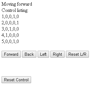
We do some parsing of the data received and then to control the car, we can use a counter based system so that we won’t ever repeat the same action and then list the actions to take. For example – 5,0,0,1,0 would mean the counter is at 5, we don’t move left (0), don’t move right (0), move forward for 1 step (1) and don’t move back (0). We pulse a pin and read the pin on the RC car side. Download ATtiny2313_SIM900A_GPRS
As you saw the video, I’m controlling my RC car via a webpage through some buttons, it take a few seconds for the car to move. The SIM900A has the capability of using TCP/UDP to connect to your server, so instead of using HTTP with the overheads you could keep polling your server even quicker than I was. There’s also an FTP option too so you could transfer say camera images.


error 603
pls do help