It’s been a few years since I’ve updated the hardware/software for Standalone Temperature/Voltage Logger but my recent Mini Temp Logger (MTL) project has made me think about improvements that I could also put back into the SATVL so there’s just a few quick things worth mentioning for the v1.3 update.
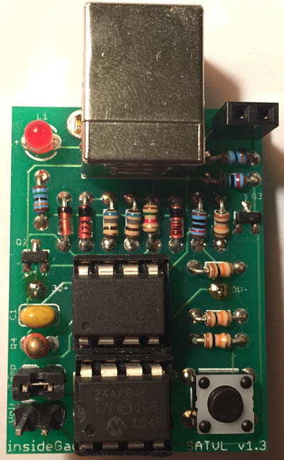
There has been a small hardware change, the 2 diodes have been removed which now allows for up to ~28V input voltage logging and the automatic voltage switcher has also been updated like I designed in the MTL, the PCB’s size was reduced slightly too. The reason for the 2 diodes was to protect against high input voltages because I believed that if we exceeded the 1.1V ADC reference voltage that the ATtiny would be damaged.

However after careful reading of the datasheet it turns out that all that would happen is it would read close to max value of 1023 so all is good.
// Use watchdog sleep for ~2.5 seconds to capture button presses
for (uint8_t x = 0; x < 9; x++) {
	watchdog_sleep(T250MS);
}

// Button was held down
if (buttonPressed == 1 && buttonReleased == 0) {
	PORTB |= (1<<ledPin); // LED on
	watchdog_sleep(T2S);
	PORTB &= ~(1<<ledPin);
	if (buttonReleased == 1) { // If button is released after LED is on, change delay time
		functionSelect = CONFIGDELAY;
		delaySeconds = 0;
		delayMinutes = 0;
		delayHours = 0;
		delayDays = 0;
	}
	else { // Button held down for 2 seconds more, change the logging mode
		functionSelect = CONFIGFUNCTION;
		loggingFunction = blankEEPROMByte;
		watchdog_sleep(T4S); // Wait until button is released
	}
}

// Start logging if button was pressed 3 times
else if (buttonPressed == 3) {
	functionSelect = STARTLOGGING;
	dataCount = 0;
	blinkLed(3, T500MS, 0);
}
Changing the delay times/function’s code wasn’t laid out as it could have been so I’ve reworked it, we now keep count of button presses and releases. Instead of having a long watchdog delay time, we quickly loop a few times with short watchdog delays and that allows us to capture if the button was pressed multiple times while still saving power instead of using a timer. We then sleep again and determine which function to execute, from 48 lines to 30 lines now.
uint8_t buttonPressedStored = buttonPressed;
while (true) { // Sleep for 4 second after each button press
	watchdog_sleep(T4S);
	if (buttonPressedStored != buttonPressed) {
		buttonPressedStored = buttonPressed;

		if (functionSelect == CONFIGDELAY) {
			delayTime++;
			cbi(GIMSK,PCIE);
			blinkLed(1, T250MS, SKIPLEDOFFDELAY);
			sbi(GIMSK,PCIE);
			if (delayTime > 11) { // Incorrect value
				delayTime = 255;
				blinkLed(1, T2S, SKIPLEDOFFDELAY);
			}
		}
		...
	}
	else {
		break;
	}
}
When doing the actual configuration I’ve changed it so once the button presses have been done, you wait 4 seconds and the configuration will be stored.
USB_PUBLIC uchar usbFunctionWrite(uchar *data, uchar len) {
	...
	delaySeconds = replyBuf[0];
	delayMinutes = replyBuf[1];
	delayHours = replyBuf[2];
	delayDays = replyBuf[3];
	loggingFunction = replyBuf[4];

	eeprom_write_byte((uint8_t*) delayTimelocation, delaySeconds); // Seconds
	eeprom_write_byte((uint8_t*) delayTimelocation+1, delayMinutes); // Minutes
	eeprom_write_byte((uint8_t*) delayTimelocation+2, delayHours); // Hours
	eeprom_write_byte((uint8_t*) delayTimelocation+3, delayDays); // Days
	eeprom_write_byte((uint8_t*) loggingFunctionlocation, loggingFunction); // Function
Instead of just having it be configured by buttons, I’ve borrowed some of the A25TTL code to have it all be configured by the PC too.
// Wait the delay time
int delayCount = delaySeconds;
while (delayCount != 0) { // Seconds
	if (delayCount >= 8) {
		watchdog_sleep(T8S);
		delayCount -= 8;
	}
	if (delayCount >= 4) {
		watchdog_sleep(T4S);
		delayCount -= 4;
	}
	else if (delayCount >= 2) {
		watchdog_sleep(T2S);
		delayCount -= 2;
	}
	else {
		watchdog_sleep(T1S);
		delayCount--;
	}
}
...
ISR(PCINT0_vect) {
...
if (functionSelect == STARTLOGGING) { // Reset AVR
	watchdog_reset_16ms();
}
I’m also using the A25TTL delay time style and the easiest way to break out of the logging loop in this case is to reset the AVR if a button is pressed.
uint8_t eepromMemsize __attribute__ ((section (".noinit")));
...
void setup(void) {
	...
	// Check if we were reset by a POR, then initialise the EEPROM variable
	if (MCUSR & (1<<PORF)) {
		eepromMemsize = blankEEPROMByte;
		MCUSR = 0; // Clear MCU register
	}

	// Turn off watchdog
	MCUSR &= ~(1<<WDRF);
	WDTCR |= (1<<WDCE) | (1<<WDE);
	WDTCR = 0;
	...
Once the watchdog reset occurs when the AVR resets we check to see the MCUSR register to see if we were reset by a power on reset which means it wasn’t the watchdog, then and only then will we reset the EEPROM memory size variable and we turn off the watchdog as we could keep resetting ourselves. The EEPROM memory size variable has been declared as a no initiliase variable which prevents the AVR from changing the value at all unless we say otherwise.
Apart from all of these changes everything remains pretty much the same. Download Standalone_Temperature_Voltage_Logger_v1.3_Rev_1


I was wondering if you’ve thought of moving to the interrupt free V-USB described at https://cpldcpu.wordpress.com/2014/03/02/interrupt-free-v-usb/
Supposedly it uses less memory (important for the tiny line of chips) and speeds up data transmission.
Hi Jonathan,
Thanks for bringing that up, I may look at using that in the near future to see how good the speed increase really is.
So can I alter the units I have to incorporate these improvements?
Yes if you have a suitable programmer like USBTinyISP or USBASP.