A while ago I bought ten 8×8 LED matrix from Ebay for about $7 and was thinking what I could do with them. Initially I was going to hook them up in a 3×3 arrangement but thought I could a better use if I connected them all together in a row to display text and potentially I could make this all wireless. Also I could use this to display the time as 10 LED matrices are just enough to fit the time, e.g, 12:34:00PM.
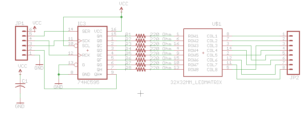
I milled out a quick board to mount the LED matrix, 595 shift register, connected it to an ATtiny84 and got it to a working point. It wasn’t really worth my time to mill out 9 more so a few weeks later the PCBs arrive and I start putting everything together.
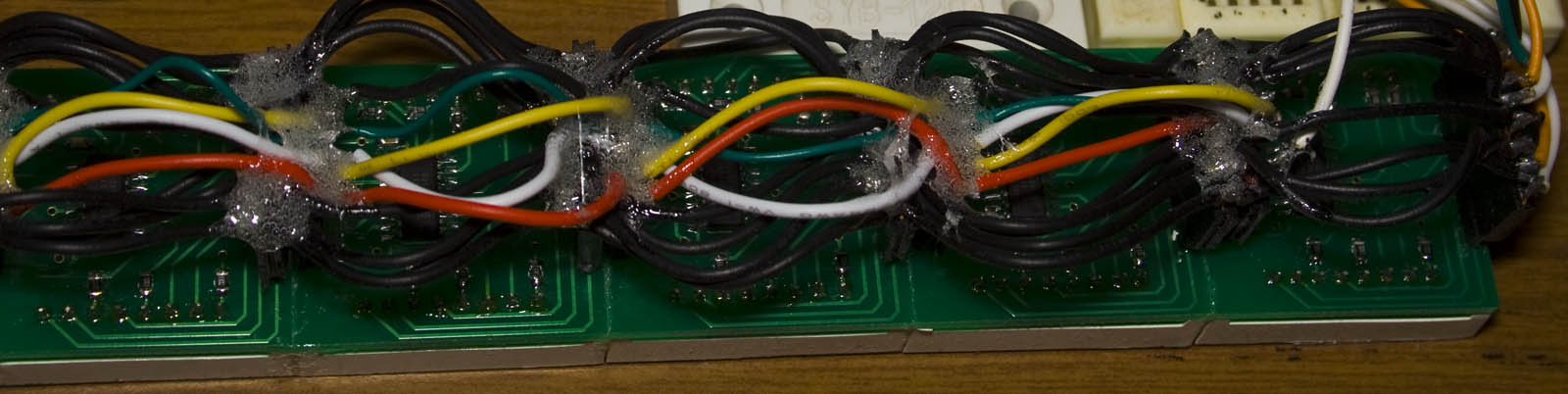
On the PCB there were some headers which would connect each matrix to each other but what I didn’t realise is that connecting the boards together was a very long process as I had to individually wire each header to each other, a few hours later and it’s done. If I were to re-do this project I would have laid out the PCBs better so they could just connect to each other without wires.
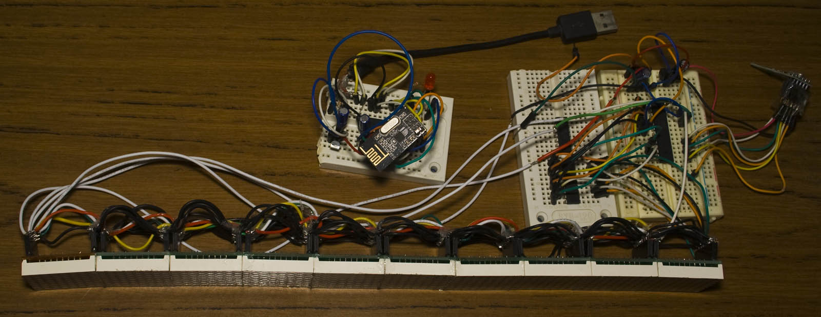
I was able to re-use some of my LED matrix code from the AT Mini Matrix Ctrl and initially tested 2 matrices together and used the ATtiny to sink the LEDs. Download ATtiny84_LED_Matrix_Test. Once I got to 3-4 matrices I started to notice some slow down when scrolling the text so I bumped the clock speed to 8MHz and that sorted it out and when connecting 10 matrices together I used an ULN2803A to sink the current and switched over to the ATmega for more pins.
Transmitter
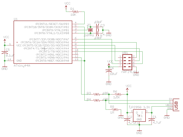
The transmitter uses an ATtiny84 with a 16MHz crystal, runs V-USB and uses the nRF24L01. We have 3 actions that we can send over the wireless – program, execute and wakeup (similar to the RGB Wifi Controlled LED).
// This gets called when data is sent from PC to the device
USB_PUBLIC uchar usbFunctionWrite(uchar *data, uchar len) {
	...
	if (dataReceived == dataLength) { // Once all data is received
		send_text = true;
	}
	return (dataReceived == dataLength); // 1 if we received it all, 0 if not
}
...

usbPoll();
if (send_text == true) {
	text_size = replyBuf[0]; // Wake up LED text
	mirf_send_wakeup(text_size, 8);

	_delay_ms(1000); // Wait a little bit before sending the text data
	mirf_transmit_data();

	_delay_ms(500); // Execute the text
	mirf_send_execute();
	send_text = false;
}
While we’re polling the USB and once we receive the complete data by checking if send_text is true (I say complete because USB doesn’t always transfer the whole data all at once, took me a little while to find that out) then we send a wake up packet, transfer the data which is entered from the PC and then send the execute command.
data_out[ACTION] = WAKEUP;
data_out[MSG_SIZE] = msgsize;
data_out[SPEED] = speed;
...
// Send for about ~1 second
for (uint8_t x = 0; x < 255; x++) {
    mirf_CE_hi; // Start transmission
    _delay_us(15);
    mirf_CE_lo;
    _delay_ms(5); // Wait for transmission/re-transmit
    mirf_config_register(STATUS, 1<<MAX_RT);
}
Here’s the wake up code, all we do is transmit the same packet for 1 second. We also include the text message size that we will be sending (up to 250 bytes) and the speed which I have pre-programmed in a variable as I don’t need that to change.
uint8_t ledMsgCounter = 1;
data_out[ACTION] = PROGRAM;
while (ledMsgCounter < text_size) {
	for (uint8_t x = 1; x < mirf_PAYLOAD; x++) {
		data_out[x] = replyBuf[ledMsgCounter];
		ledMsgCounter++;
	}
	...
	mirf_CE_hi; // Start transmission
	_delay_us(15);
	mirf_CE_lo;
	_delay_ms(2); // Wait for transmission/re-transmit/receiver to read out data
	mirf_config_register(STATUS, 1<<MAX_RT); // Reset max retries
}

...
data_out[ACTION] = EXECUTE;
mirf_CE_hi; // Start transmission
_delay_us(15);
mirf_CE_lo;
_delay_ms(2); // Wait for transmission/re-transmit
When transferring the text over wireless we can only send 32 bytes at a time so we’ll just break up the string and loop until it’s all been sent and the receiver will put it back together. Then we just send the execute command.
Transmitter USB Program
printf("Enter text: ");
char text_input[251];
read_chars(text_input, 250);

char usb_data[254];
usb_data[0] = strlen(text_input);
memcpy (&usb_data[1], text_input, strlen(text_input)+1);

usb_control_msg(handle,
	USB_TYPE_VENDOR | USB_RECIP_DEVICE | USB_ENDPOINT_OUT,
	USB_TEXT, 0, 0, usb_data, 254, 5000);
In the program which transmit our input over the wireless there isn’t much to it, we grab the string length that was entered and put that in the first byte of the usb_data variable and copy the text to the 2nd byte of the usb_data using memcpy.
Receiver
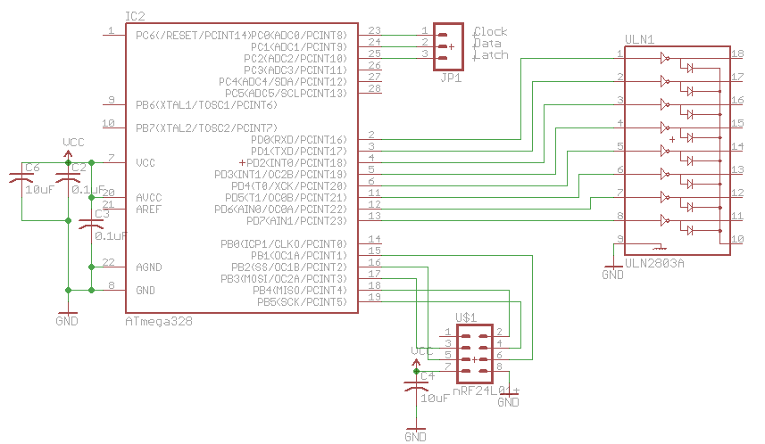
In the receiver we listen for packets for 10 ms and then sleep for 1 second.
// Start the timer for 8 seconds
timedOut = false;
TCNT1 = 0;
sbi(TIMSK1, TOIE1); // Enable overflow interrupt
TCCR1B = (1<<CS12) | (1<<CS10);

RX_POWERUP; // Power up to receiver mode
...
uint8_t ledMsgCounter = 0;
while (1) {
	while (mirf_rx_fifo_empty()) { // While RX FIFO is empty, waiting for a packet
		_delay_us(50);
		if (timedOut == true) {
			POWERDOWN;
			TCCR1B = 0; // Stop timer
			return 0;
		}
	}
	...
	if (data_in[ACTION] == PROGRAM) { // Check if it's a program packet
		for (uint8_t x = 1; x < mirf_PAYLOAD; x++) {
			if (ledMsgCounter < ledMsgSize) {
				ledsMessage[ledMsgCounter] = data_in[x];
				ledMsgCounter++;
			}
		}
	}
	else if (data_in[ACTION] == EXECUTE) {
		POWERDOWN;
		TCCR1B = 0; // Stop timer
		return 1;
	}
}
Once we receive a wake up packet, we start an 8 second timer and listen for the program packets. I used to check for the RX_DR pin on the nRF24L01 but this time I might as well use the RX Fifo to read out packets so we don’t have to clear the fifo like I used to (so we knew we got new packets).
ledLocation = 0;
for (uint8_t x = 0; x < ledMsgSize; x++) {
	// Append the matrix with the next text
	append_text();

	// Move the matrix to the left 8 times
	for (uint8_t x = 0; x < 8; x++) {
		move_LEDs();
		// Light up the LEDs a few times to fill in time
		for (uint8_t i = 0; i < ledSpeed; i++) {
			light_LEDs();
		}
	}
}
clear_LEDs();
Once the execute packet is received we run the loop for displaying the text. There’s more happening in the background like converting the text received whether uppercase or lowercase to be all uppercase, accounting for spaces plus all the shifting of data but I’ll leave that up to you to explore as I’ve explained some of this before. Download 8x8_x10_LED_Scrolling_v1.0


