Lately my blog has been focused on quadcopters / RC cars and here’s another little one, I’ve been wanting to try out Acro mode but would rather not crash a whole lot to test it out. There’s a program called FPV Freerider which lets you simulate the quadcopter on a few different maps. Normally you would use a Flight Simulator Cable however I didn’t want to wait and they were out of stock locally.
I happened to stumble upon Giuseppe’s Urso’s Blog which had some code for this exact purpose but for some reason only my first channel was working with my Turnigy iA6 receiver. The format being sent by 9600 baud serial was the FMS PIC 9600 which involves a special byte mixed in with the number of channels, another byte for buttons and then each channel has it’s own byte ranging from 0 to 255. Now that we have the format, I can write some code.
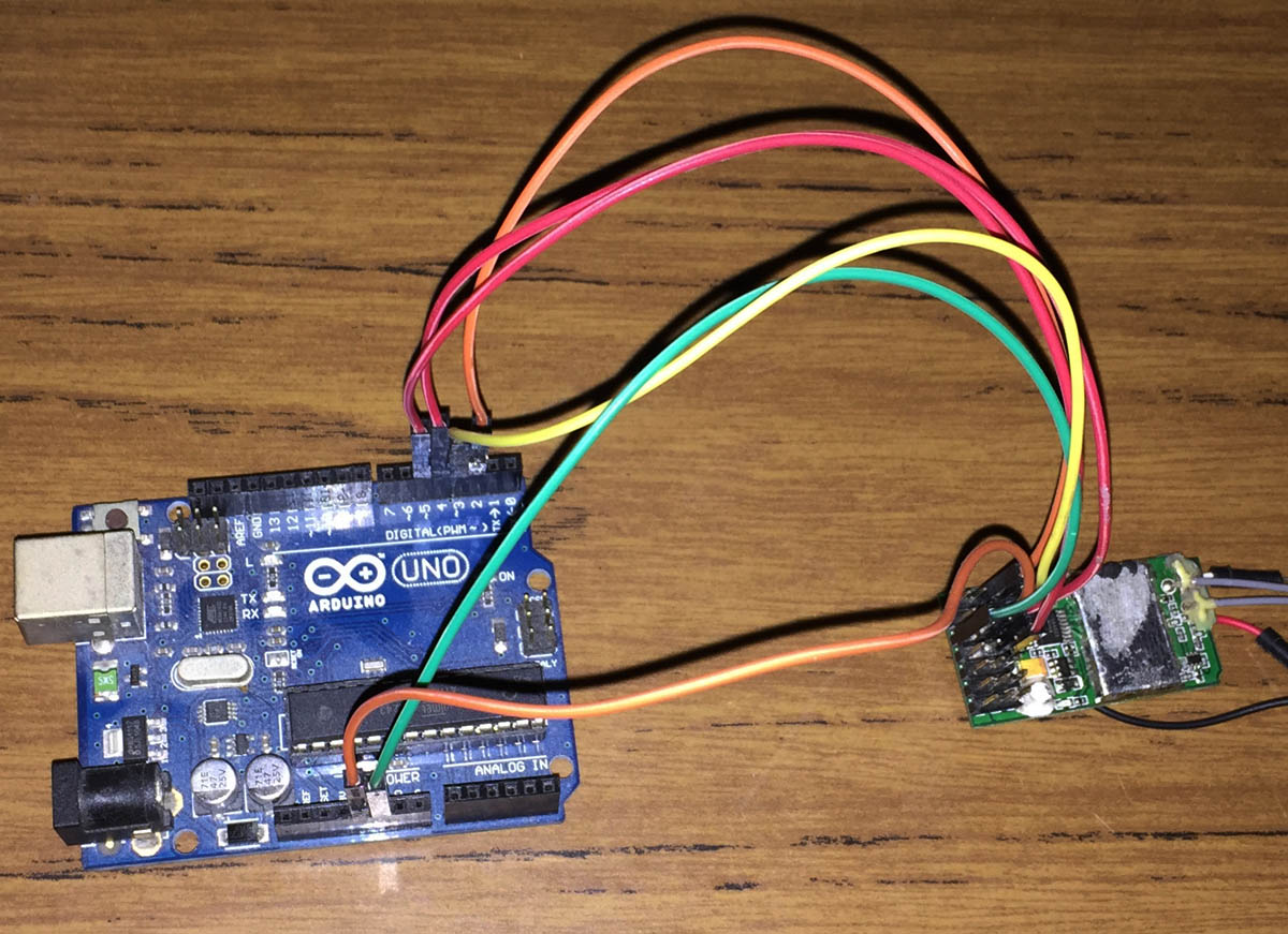
I found that my iA6 receiver outputs all it’s channels at the same time, i.e all at the same time and not one after another like some other receivers might, it actually makes it easier for us as all we need is an interrupt on any of the pins and then we start counting. Connect RX channel 1 to Arduino pin 2, RX channel 2 to Arduino pin 3 and so on.
#define RX_CHANNELS 4

volatile uint16_t ch1Result = 127;
...

void setup() {
  Serial.begin(9600);

  // Set inputs
  for (uint8_t x = 2; x < RX_CHANNELS + 2; x++) {
    pinMode(x,INPUT);
  }

  // Attach interrupt to pin 2 as rising
  attachInterrupt(0, time_channels, RISING);

  // Reuse Timer1 to count the microseconds after pin 2, etc go high
  TCCR1A = 0;
  TIMSK1 = 0;
  TIFR1 = 0;
  TCNT1 = 0;
  TCCR1B = (1<<CS10);
}
After playing around with the Arduino micros function, it had glitching every few results so I used the timers directly. We setup the pins as inputs, attach the interrupt INT0 to pin 2 to only trigger when the pin goes high and reset the timer to the default.
void loop() {
// FMS PIC 9600 format
// 0xF0 + Number of RX channels
Serial.write(0xF0 + RX_CHANNELS);
// 0x00
Serial.write((byte)0x00);
// The 4 channels
Serial.write(ch1Result);
Serial.write(ch2Result);
Serial.write(ch3Result);
Serial.write(ch4Result);
}
// Check how long each channel is high for
void time_channels(void) {
TCNT1 = 0; // Reset counter
int ch1Time = 0;
...
// While any of our 4 channels are high, check each channel and update it with the current timer value
while ((PIND & ((1<<PD2) | (1<<PD3) | (1<<PD4) | (1<<PD5)))) {
if (PIND & (1<<PD2)) {
ch1Time = TCNT1;
}
...
}
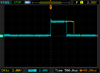
// Convert timer values to ~950 - 2000uS times
ch1Time = ch1Time / 16;
...
// Map the times to 0 to 255
// Adjust these values so your endpoints correspond close to 0 if you move the stick one way and close to 255 the other way
ch1Result = map(ch1Time, 980, 2020, 0, 255);
ch2Result = map(ch2Time, 980, 1994, 0, 255);
ch3Result = map(ch3Time, 980, 1994, 0, 255);
ch4Result = map(ch4Time, 980, 2000, 0, 255);
}
In the loop we just repeatedly send our results via serial. Once an interrupt occurs we reset Timer1 to 0 as we’ll begin our counting. When any of our channels are high, we update that particular channel with the current timer value and once all channels go low we then convert our timer value (which ticks over every clock cycle) to microseconds which usually becomes 950 to 2000 or so. We use the map function to map our range to 0 to 255, this part might need to be changed depending on your controller ranges and we’re done. Download iA6_FMS_Serial_v1.1 (recommended) or iA6_FMS_Serial v1.0
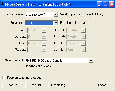
The other piece of software that you’ll need is PPJoy to convert the serial data into virtual joystick control, run PPJoyCom, select your COM port and select FMS PIC 9600 baud (Generic).
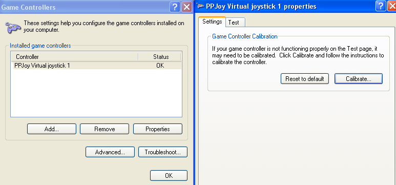
Then you need to calibrate your game controller in Windows so when moving your controller it maps correctly. I was getting a bit of overshoot where turning right too much would result in it appearing in the middle which I correct via trimming and endpoint adjustment.
https://www.youtube.com/watch?v=BwiuF_3e7CY
The last step is to run FPV Freerider and do a calibration in there too and you’re all set. I’ve flown a bit in the simulator already and am starting to get the hang of it but when I tried on the quad itself, it wasn’t quite the same, I think I need to adjust my rates.


Neat idea!
I think theres a small bug:
for (uint8_t x = 2; x < RX_CHANNELS; x++) {
This will only set pins 2 and 3 to input mode rather than 2-5. I don't think it matters though since the digital pins always default to inputs anyway.
Hope it helps
Oops, my bad, thanks for that Craig!
Hi, i’m trying by 4 days to connect my arduino to the same reciever you have, i uploaded the arduino code, installed ppjoy, but once i’m in ppjoyCOM it says 😐
Virtual joystick 1 – successfully opened joystick
Serial Port : 15 Error 2 opening port
Serial Protocol : waiting for stream init
i tried also other methods, unojoy, vjoy and so on… nothing seems to work 🙁 please heeeelp!
Hi Massimo,
I think the first problem to solve is that the serial port isn’t opening for you, even with the blink sketch on the Arduino it should still open the serial port. I’m guessing you have already tried changing the port to match the Arduino software.
I’m on Windows 7 using the old PPJoy software. Have you also run the command below and then rebooted? I have to leave that set to on for PPJoy to work even after it’s installed.
bcdedit -set testsigning on
Hi Alex, first, thanks fo the fast reply. In the weekend i will try on a fresh pc install. I’m using WIndows 8 64 bit, the thing is that, from arduino program i can read serial com with no problem, but as soon i as i switch to ppjoy the com port is not working and i cannot see any Joystick in windows devices. I tried also with UnoJoy, as always , inside arduino program i can read the serial port, but when i turn it into a joystic i just see flashing buttons and all the commands moving really fast. I cannot understand what is the problem, seeing everyone is able to use the reciever with the pc, execpt me.
Hmm, can you also try right clicking PPJoy or UnoJoy and running as administrator? Also try disabling UAC and rebooting.
Make sure that the Arduino software is closed because it likes to probe COM ports when it’s open and can cause issues with software that has the COM port open already.
Thanks again for the reply, i will try disabling UAC (even if i think is already deactivated). I tried always to close the arduino program, because i had the problem of the “busy” port. In any case i will try this weekend to see if i can find the problem.
THANKS VERY MUCH FOR THE HELP !!! MUCH APPRECIATED !!
Update on my situation, i managed to solve the problem with PPjoy, i think was a matter of .HEX file on the arduino. In fact when i restored my ARDUINO UNO R3 with the hex you can find in the Arduino folder ( the program used to compile code), and uploaded the iA6_FMS_serial_V1.1 , ppjoy suddently picked up the serial and was able to read my arduino as a JOYPAD! only “problem” i’m trying to figure out is why i cannot see all the channel of my radio, i have a MODE 2 radio, could that be the problem? do i need to modify the code in Arduino ?
Thanks again!
Massimo
Hi Massimo,
Good to hear you got it working, a strange fix to the problem, maybe somehow the boot loader was programmed with an older or different firmware.
It depends how many wires you have going from the receiver to the Arduino and the code, by default it should have 4 which cover roll, pitch, yaw and throttle. If you would like to add more, you just have to modify the code to check for the additional channels, it should be relatively straight forward (you can copy what’s already been done).
Hi there, I’ve uploaded the arduino sketch and ppjoy says it is reading the serial stream. However, it only works for the one channel that is connected to pin 2. It doesn’t work for the other channels. I tried swapping the wires with pin 2 and then only a different channel would work. Inputs 3,4,5 are not doing anything. I tried adding:
pinMode(3,INPUT);
pinMode(4,INPUT);
pinMode(5,INPUT);
but this didn’t do anything. I have trying to find a way to connect my turnigy 9x for a long time so any help will be greatly appreciated!
Thanks
Hi Gautam,
Just checking if your receiver is outputting PPM? When you connect to pin 2, do you see the joystick move properly as the stick moves?
I thought I’d quickly add that I also used the serial monitor and found that only the channel connected to pin 2 was working. The rest were idle at 65301.