From the last part, we looked at using the Si4432 module for communication between the sensors and server with the ESP8266 Wifi module as our web server. Today we’ll look at the Atmel CryptoAuthentication ATSHA204A device which will let us use truly random numbers and use the HMAC function with a private key (stored securely on the device) which means no hashing libraries will be required for the ATtiny.
The way I intend to use the device is for it to return a 32 byte random number which we can change 1 byte of so the server and client can communicate with that 1 byte, feed it into the device which will generate a HMAC from that random number and a private key.
There are plenty of other use cases described in this Atmel PDFs:
Atmel-8794-CryptoAuth-ATSHA204-Product-Uses-Application-Note
Atmel Crypto Products REAL.EASY Training Manual 2Q2015 r6
I’m using the I2C version which should be quicker to access and easier to use than the the 1 wire version, should save us a little bit of battery life too. Before we hook it up to the ATtiny, we need to test it so we’ll be using the Arduino, there are one wire library examples out there but none for the I2C version. Atmel also has some libraries available for the CryptoAuthentication product suite however there was a lot of functions and jumping around so the only code I used from that library was the CRC function.
The device contains 3 zones:
– 16 data slots where you can load a 256bit key to each slot
– Configuration zone includes allows you to set how the data slot keys can be used, whether the keys can be read/written, a counter to provided limited use of the data slot keys, the unique serial number and programmable I2C address to name a few.
– One time programmable (OTP) zone contains 64 bytes that can be used as read only memory.
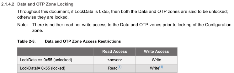
The configuration zone and data slots/OTP can be locked to block any writes to them, this is useful if you don’t want keys re-programmed and disallow how each data slot can be used. In order to write to the data slots, the configuration zone needs to be locked.
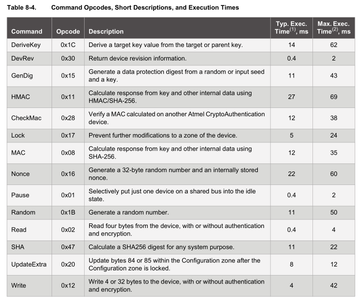
Timing
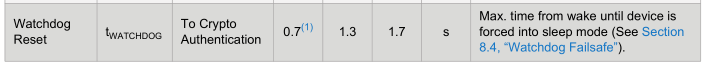
For each function, we have to wait for the device to perform it, the device has a watchdog timeout of 700ms to 1.3 seconds, so after the device wakes up, we have 700ms before it goes back to sleep. For us the main functions we will use are HMAC (69ms max), Nonce (60ms max) and Random (50ms max).
Sending/Receiving data format
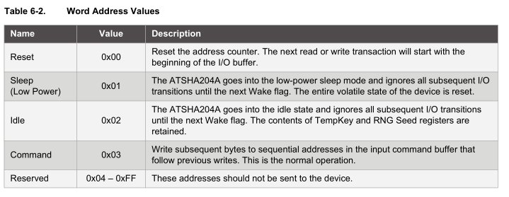
There are basic functions that you can send to the device such as reset, sleep, idle, etc. For example, sending sleep is as easy writing the device address and the command.
soft_i2c_master_start(cryptoauth_address | I2C_WRITE);
soft_i2c_master_write(FUNCTION_SLEEP);
soft_i2c_master_stop();
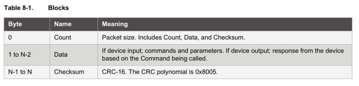
When sending a command to the device, there is a bit more to it, the following table explains it nicely. You send a packet which contains the packet length, opcode, parameters, data and checksum.
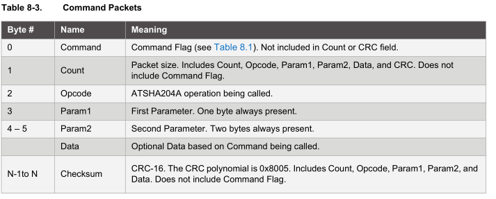
The device contains a FIFO buffer for when you wish to read the results of your commands. The packet format is count, data and checksum.
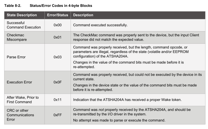
If the data returned is a single byte (formatted like count, single byte, 2 byte crc) such as when a command has been executed successfully (0x00), the status will be one of the below.
Wake up the device
First things first, we need to wake up the device, this is done by pulling the SDA line low for 1 ms and then leaving it high for 3ms. The device’s buffer will contain 0x04 as the count as there are 4 bytes, 0x11 as the data byte which shows the device is awake and the CRC of 0x33, 0x43.
This is where my problems started, it would acknowledge the device address but would give random data for other commands I was trying. I tried another I2C library without success and then tried doing it properly by using pull-up resistors and it worked fine, I need to use them all the time.
Read the configuration zone
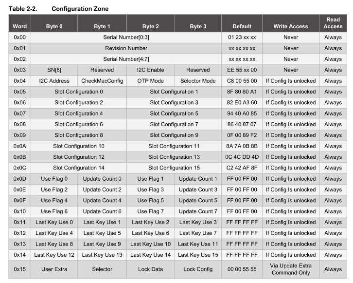
Just to check that everything is working properly, we can read the configuration zone before we write to it, lock it so then we can add in the keys to the data slots. The configuration zone has quite a lot of data and we can read 4 or 32 bytes at a time.
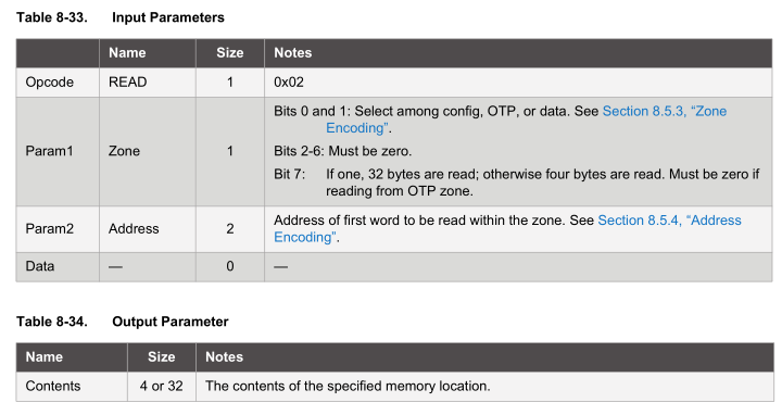
If we wish to read the first 32 bytes, the packet we send to the device needs to have 0x02 as the opcode, the config zone bits 1 and 2 are zero for config zone and for 32 byte reads we set bit 7 for param1, the start address will be 0x00 plus another 0x00 as it’s 2 bytes for param2 and no other data needs to be sent; the output will be 32 bytes and placed on the buffer of the device which we need to read out.
void sha204a_read(uint8_t address, uint8_t readCount) {
	data_out[0] = FUNCTION_COMMAND; // command
	data_out[1] = 7; // count (included in count)
	data_out[2] = COMMAND_READ; // read
	data_out[3] = ZONE_ENCODING_CONFIG | readCount;
	data_out[4] = address;
	data_out[5] = 0;

	sha204c_calculate_crc(5, &data_out[1], crc); // crc starts at count

	soft_i2c_master_start(cryptoauth_address | I2C_WRITE);
	for (uint8_t x = 0; x < 6; x++) {
		soft_i2c_master_write(data_out[x]);
	}
	soft_i2c_master_write(crc[0]);
	soft_i2c_master_write(crc[1]);
	soft_i2c_master_stop();

	delay(4);
}

...

sha204a_wakeup();
sha204a_read(0, READ_32_BYTES);
sha204a_read_buffer();
sha204a_sleep();
We can put it all in a function as we will call it multiple times, firstly construct our array with the appropriate values, then starting from the 2nd element of the array pass it to the crc calculator which pops it’s result to the crc[] array. We send all the data to the device and wait 4 ms as per the datasheet.
To read the first 32 bytes of data, we wakeup, request a read of 0x00 of 32 bytes, read the buffer and then sleep. We need to put the device to sleep or idle so that we can send another lot of read commands to it, otherwise it may timeout on us.
void sha204a_read_buffer(void) {
	if (soft_i2c_master_start(cryptoauth_address | I2C_READ)) {
		uint8_t x = 0;
		data_in[x] = soft_i2c_master_read(0);
		x++;

		while (x < (data_in[PACKET_COUNT] - 2)) {
			data_in[x] = soft_i2c_master_read(0);
			x++;
		}

		data_in[x] = soft_i2c_master_read(0);
		x++;
		data_in[x] = soft_i2c_master_read(1);
		soft_i2c_master_stop();

		// Check CRC matches
		if (sha204c_check_crc(data_in) == true) {
To read the buffer, we send the device address, read the first byte which contains the length of the packet which we use to read the remaining bytes plus the 2 byte CRC at the end. We can pass all this through the check crc function to check the crc is valid on that packet. Now that we know how to write to and read from the device, the other commands are easy as long as we understand what they do.
Count = 0x04, Data = 0x11, , CRC = 0x33, 0x43 CRC Ok
Count = 0x23, Data = 0x01, 0x23, 0x1F, 0x69, 0x00, 0x09, 0x04, 0x00, 0xE2, 0x69, 0x9E, 0xD3, 0xEE, 0x0F, 0x01, 0x00, 0xC8, 0x00, 0x55, 0x00, 0x80, 0x80, 0x80, 0xA1, 0x82, 0xE0, 0xA3, 0x60, 0x94, 0x40, 0xA0, 0x85, , CRC = 0xD9, 0x60 CRC Ok
...
Configuration Zone
01 23 1F 69
00 09 04 00
E2 69 9E D3
EE 0F 01 00
C8 00 55 00
8F 80 80 A1
82 E0 A3 60
94 40 A0 85
86 40 87 07
0F 00 89 F2
8A 7A 0B 8B
0C 4C DD 4D
C2 42 AF 8F
FF 00 FF 00
FF 00 FF 00
FF 00 FF 00
FF 00 FF 00
FF FF FF FF
FF FF FF FF
FF FF FF FF
FF FF FF FF
00 00 00 00
After a bit of parsing, we can issue “read” in the serial monitor of the Arduino and it will return to use the configuration nicely printed out.
Write the configuration data
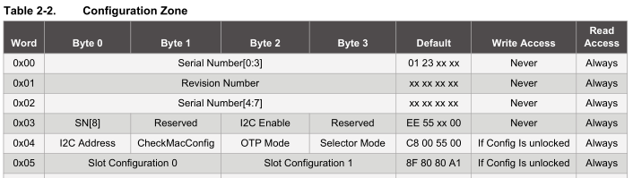
The section we are concerned with is the slot configuration to make sure the keys stored in the data zone can’t ever be read out or written to once the data zone is locked. Each data zone slot has it’s own configuration and we will focus on Slot Configuration 0 which corresponds to Data Slot 0.
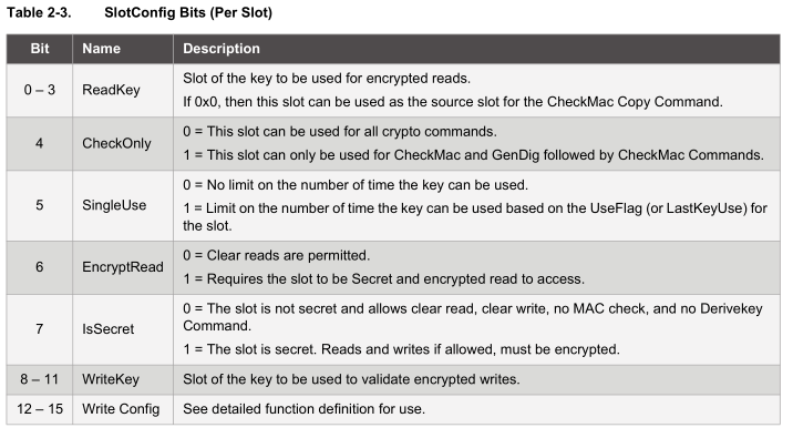
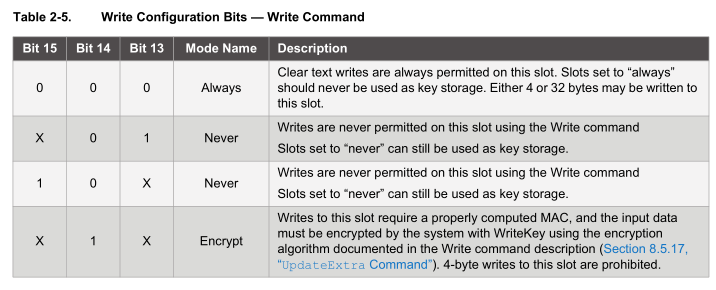
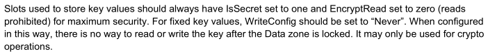
As you can see there are lots of different options, at the minimum we need to set the isSecret bit on and bit 15 to on to set write as never so the keys can’t be read or written which gives us 0x80 0x80.
The write configuration bits only take effect after the data zone has been locked, so technically if you were trialing the device out, you don’t have to lock the data zone, you could always write a new key to the slot but never be able to read it out.
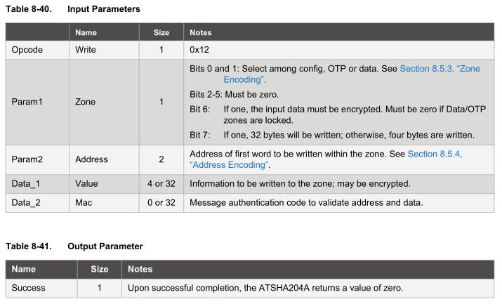
data_out[0] = FUNCTION_COMMAND; // command
data_out[1] = 9 + 2; // count (included in count + crc)
data_out[2] = COMMAND_WRITE;
data_out[3] = ZONE_ENCODING_CONFIG;
data_out[4] = 0x05; // Address
data_out[5] = 0;

data_out[6] = 0x80;
data_out[7] = 0x80;
data_out[8] = 0x80;
data_out[9] = 0xA1;
Writing to the configuration zone is done is 4 byte chunks, so 0x05 will be our address and our bytes to write 0x80, 0x80 and we’ll leave the other 2 bytes 0x80 0xA1 the same as before. We verify the change was made by checking if we received a value of 0 and also re-read the configuration zone.
Lock the configuration zone
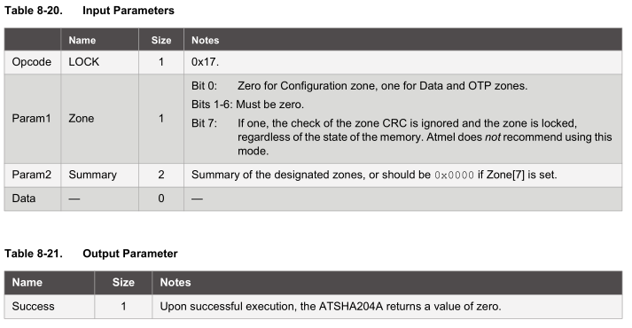
data_out[0] = FUNCTION_COMMAND; // command
data_out[1] = 7; // count (included in count)
data_out[2] = COMMAND_LOCK;
data_out[3] = ZONE_LOCK_CONFIG | LOCK_NO_CRC_CHECK;
data_out[4] = 0;
data_out[5] = 0;
Now we can proceed with locking the configuration zone by selecting the zone and for simplicity we’ll set bit 7 so the crc check will be ignored as I’ve already verified that the config data is correct.
Write the data zone key and lock the data zone
The device will now let us write to the data zone, we’ll just be writing to data slot 0 with our 32 byte key which will be used for the HMAC, the same key will need to be used for both the client and server. For a high security key, it should be random, you could essentially use the random function of this device and load that random number as your key!
data_out[0] = FUNCTION_COMMAND; // command
data_out[1] = 7 + 32; // count (included in count)
data_out[2] = COMMAND_WRITE;
data_out[3] = ZONE_ENCODING_DATA | READ_32_BYTES;
data_out[4] = SLOT_0;
data_out[5] = 0;

uint8_t privkey[32] = {0x22, 0x24, 0x25, 0xB9, 0xA3, 0x6C, 0x44, 0x53,
			0x5F, 0xA1, 0x32, 0x9F, 0x37, 0xCC, 0x6E, 0x49,
			0x45, 0x02, 0x20, 0x9E, 0x5D, 0xDD, 0x02, 0x32,
			0xF3, 0xC5, 0x4E, 0x1A, 0x3A, 0x3E, 0x44, 0x55};

for (uint8_t x = 0; x <= 32; x++) {
   data_out[x+6] = privkey[x];
}
When writing to the data zone, we use 32 byte writes and we have our private key in the array then we just check that the result received was 0 once again.
data_out[0] = FUNCTION_COMMAND; // command
data_out[1] = 7; // count (included in count)
data_out[2] = COMMAND_LOCK;
data_out[3] = ZONE_LOCK_DATA_OTP | LOCK_NO_CRC_CHECK;
data_out[4] = 0;
data_out[5] = 0;
For maximum security we can now lock the data zone (but you don’t need to if you wish to change the key later on when testing).
Request random number
Now that the set up is all complete, we can request a 32 byte random number from the device.
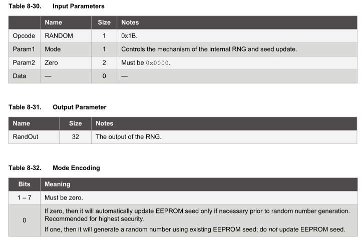
As the datasheet advises, for highest security we should leave bit 0 of the mode set to 0 so it updates the EEPROM seed. We can read the 32 byte random number back after 50 ms.
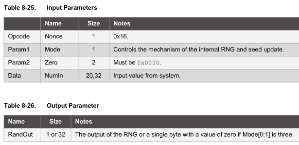
Nonce function
The nonce function allows you to combine an input from the MCU with an internally generated random number to produce a hash. The nonce function can also be used in pass-through mode in which we load it with a 32 byte number which doesn’t get hashed, this will be handy for us though keep in mind its subject to replay attacks (but not in the way my system will operate).
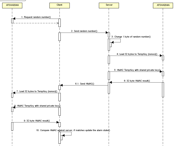
For my implementation of the alarm system, the client will send the server the 32 byte random number, the server will change 1 byte of that random number to the alarm state, feed that 32 byte number into the nonce function in pass-through mode and then we can HMAC it. The server will then send the HMAC back to the client along with the byte that it changed so that it can verify the alarm state is correct.
uint8_t randomnumber[32] = {0x71, 0xE2, 0x34, 0xF3, 0xDF, 0xD4, 0x51, 0x3B,
			0x6E, 0x83, 0x6D, 0xF4, 0xC7, 0xBD, 0xC2, 0x1B,
			0xD6, 0xE2, 0xF5, 0xA7, 0x92, 0x2C, 0x64, 0xB0,
			0x25, 0x57, 0x15, 0xC1, 0x04, 0x49, 0xA2, 0xD0};
...
data_out[0] = FUNCTION_COMMAND; // command
data_out[1] = 7 + 32; // count (included in count)
data_out[2] = COMMAND_NONCE;
data_out[3] = NONCE_PASS_THROUGH;
data_out[4] = 0;
data_out[5] = 0;

for (uint8_t x = 0; x < 32; x++) {
  data_out[x+6] = randomnumber[x];
}
...
sha204a_idle();
I’m just using a static 32 byte array for testing purposes which we feed into the device. This array is loaded into TempKey which is located in the SRAM, once we are done using the nonce function we have to set the device to idle otherwise if it goes to sleep, it will wipe the TempKey.isValid flag.
HMAC function
Now that the 32 byte number is loaded into TempKey, we can run the HMAC function.
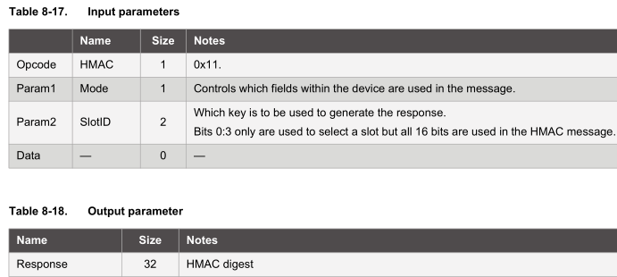
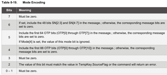
data_out[0] = FUNCTION_COMMAND; // command
data_out[1] = 7; // count (included in count)
data_out[2] = COMMAND_HMAC;
data_out[3] = 0x04; //mode, TempKey.SourceFlag, 1 = Input
data_out[4] = SLOT_0;
data_out[5] = 0;
When requesting the HMAC, we have to specify that we used pass through in the nonce function by setting bit 2 to 1 in the mode/param1. You can also include the serial number of the device in the HMAC however for my case, I shouldn’t do this as both the server and client need to reach the same HMAC result. We specify the slot number 0 which is the key we loaded up before and we receive back the 32 byte HMAC result.
In my project, the server would then send back the HMAC result with the alarm state which the client would use that along with the random number it provided the server to reach the same HMAC result.
You can download all the functions described for the Arduino here: ATSHA204A_Example
Open serial monitor at 9600 to access the ATSHA204A commands such as:
 "wake" - Tests to see if waking up the device works
 "read" - Print out the configuration zone
 "write" - Write 4 bytes to slot config 0 & 1 in the configuration zone
 "rand" - Return a 32 byte random number, it's only random if the configuration zone is locked
 "lockconfig" - Lock the configuration zone. *Be careful, once locked, it can't be unlocked*
 "lockdata" - Lock the data and OTP zones. *Be careful, once locked, it can't be unlocked*
 "loadkey" - Write a 32 byte number in slot 0, this will be our secret key. *You should change the number*
 "nonce" - Use the pass through mode to load a 32 byte number into TempKey
 "hmac" - Combines the nonce with slot 0 key to generate the HMAC result
Using the ATSHA204A device was a bigger undertaking than I thought, trying to understand how I could use the device, writing down the steps, understanding the configuration, it’s various functions and use cases, so hopefully this makes it easier for anyone trying to get started with this device.
Next I should be able to move it all over to the ATtiny84, have a client and server test with the Si4432 and try to optimise the client best so it’s never awake for too long. I was also starting to look at FHSS on the Si4432 as I thought this was needed to abide by laws, though it seems like Australia allows for up to 25mW on the 433MHz band for “non-specific applications” but I’ll still discuss it briefly, it would have been a bit more work.


Hi Alex
This post is really helpful can you give me some idea about Atsha204a’s OTP Zone.
Actually I am doing a project where my client’s requirement is crypto for firmware.
I have to use crypto when my application starts running so if someone has updated some other code to my controller with modification then my application won’t run.
Can you help me with this bcz I am reading the data sheet of crypto but it is confusing and don’t know which mode to use for what.
Regards
Harish
Hi Harish,
In your case, you would need to look at the “40. Firmware Protection” and also “45. Protecting Communication between the Crypto device and MCU” from this PDF: https://www.insidegadgets.com/wp-content/uploads/2017/04/Atmel-Crypto-Products-REAL.EASY-Training-Manual-2Q2015-r6.pdf
I haven’t looked into this myself as for my project, if physical access is achieved, it’s all over.
Hi Alex
Thanks for replying I checked what you have mentioned but my question is if I want to write a 32byte key in slot0 for once and whenever If I firmware update it the first thing which I am gonna do is to read that slot 0 data and compare it with the data which I have saved.
Regards
Harish
Hi Alex
“We verify the change was made by checking if we received a value of 0 and also re-read the configuration zone.” You have mentioned like this above but how we can read the status…or what we are going to receive value and where ??
Regards
Harish
Once we write the data to the device, we read the device buffer (function sha204a_read_buffer in the code), which could come back with something like:
Count = 0x04, Data = 0x00, CRC = 0x33, 0x43 CRC Ok
If data is 0x00, then we know the write was successful.
Now we can re-read the configuration data and see if the bytes we wrote to have changed (function sha204a_print_config in code).
Hi Harish,
That could work if you will be doing firmware updates however if anyone found out what you were doing then they could change the slot0 key. If this suits, then I would probably just use an EEPROM instead. Otherwise I believe you can tell the device to only read/write to the slot with encryption so it would be harder for users to read/write to the slot but not impossible if they had your firmware or applied some form of power analysis.
Regarding the OTP, you could use it but if you did a firmware update, you can’t program it again.
Hi Alex
I am implementing api’s by using the crypto libraries. So I got confused and your post really helped me.
So now I want to write your privkey in to my slot 0 so this is the step I am following
1] Config Write – writing 0x80 0x80 0x80 0xA1
2]Locking Config Zone
3]Writing your 32bytes private key in slot 0
4]Locking Data Zone
for each of this command I am getting 0x04 0x0f 0x23 0x42
as response
and how to unlock the locked config or data zone
If you have mention your mail Id I could have sended my code to you. Some where I am doing wrong but I am getting more confused.
Regards
Harish
Hi Alex
How can read the 32 bytes priv key data what I have stored in slot 0 ??
And can I unlock the data zone after it is locked to change my priv key ??
Regards
Harish
Once the data zone and/or config zone is locked, there is no way to unlock it. But you need to lock the config zone in order to write/read to the data zone. That’s why you need to only lock the config zone (but don’t use my 0x80 0x80 0x80 0xA1 example as my config is not suitable for your case, I think 0x00 0x00 0x80 0xA1 might work).
Remember you have 16 slots to play around with so you can set any combination you like as see which one works best but also remember reading/writing without encryption, is kind of like having an eeprom.
Hi Alex
I have done according to your configuration I don’t know how to use some other slot’s now and this is first time I am working on it and I am not able to read the private key what I have saved in the data zone but if I write using otp zone and read otp zone I can read it but their are some other problem with otp zone.
I just wanted to write some 32bytes data into any of the slot and read it.
Regards
Harish
Hi Harish,
I have played around with Slot1 and reads/writes works in clear text, please check over v2 here: https://www.insidegadgets.com/wp-content/uploads/2017/12/ATSHA204A_Example_v2.zip
Hi Harish,
0x0F means “Execution Error”, “Command was properly received, but could not be executed by the device in its current state. Changes in the device state or the value of the command bits must be made before it is re-attempted”, page 40 on the PDF.
The device is sensitive to how it’s used, you can only talk to it for a certain amount of time (1 second I think) and you need to wake it up, wait a little, read the buffer, execute your command, wait a certain amount of time depending on the command, then read the buffer out again and then put it to sleep (or wait for it to time out).
Hi Alex
I just observed something. I was reading 4 bytes of data from config zone and after that I restarted my device but now crypto is not waking up???
Regards
Harish
Hi Harish,
The only thing I can think that could have happened apart from an unknown failure is that somehow the I2C address was changed (but this in itself seem rare). See if you can make a loop to wake the device and check for all the I2C address combinations.
Hi Alex,
Sorry for the late reply I had locked my 2 crypto ic’s so left the project for a while and now bought 3 more…:)
I was reading this pdf
Atmel-8841-CryptoAuth-ATSHA204-Unique-Keys-ApplicationNote
And suggested needed your opinion about this
Regards
Harish
Hi Alex,
I am also working with ATSHA204A now. This is really helpful to me. I am also planning some
complex things with this ATSHA204A soon. I hope your help for that.
Thanks.
I have communication problem with ATSHA204A, Following is the details
Application : ATSHA204A I2C
Problem : When using with a capacitancy touch panel, it seems that the signal sent from ATSHA204A was interrupted by the touch panel,
For the touych panel scan the I2C frequenctly
History : Same security key are using in other system ( not I2C ), no problem.
When using ATSHA204A with touch panel, following was happened.
1. When start up the host machine, 80% of the chance the host machine can receive security signal from ATSHA204A.
After that there was little chance to receive the security signal successfully.
Shut down the host machine, above case happened again.
2. Taking out all other device from the I2C except the touch panel, in this case the I2C is only for touch panel. The host machine
can receive complete security signal from ATSHA204A . NO problem at all and this can be repeated for hundred times.
3. wake up process – No problem, chips wake up code was received.
I have spent a month to solve the problem but not successful.
I would be appreciated if you can send me some advice thru email.
Thanks
Herbert
herbert@makrotekglobal.com
Hi Herbert,
Just checking that you have pull up resistors for the I2C bus?
When the ATSHA204A is not responding but is waking up, have you been able to see if there is anything in the buffer? How about if you send it simple commands like reading the configuration zone?
I think you may have a few options:
– At start up, or any time the ATSHA204A is being accessed, could you change the touch panel mode to idle or sleep mode? Then change it back to the mode it was at
– If your MCU has spare pins, you could try bit banging I2C and only connect the ATSHA204A to those pins (and have pull up resistors)
Hi Alex,
In the project give, the 3rd step, before loading the challenge into TempKey, you are changing 1 byte. Doesn’t it affect the HMAC generation, as it would alter the HMAC result and Client doesn’t know which 1 byte is changed. Kindly explain.
Thanks 🙂
Hi gk,
Ah what isn’t shown is that the 1 byte changed by the server is the alarm state. The server also sends this 1 byte back to the client so that it can change the same byte like the server did and verify the HMAC matches.