I thought it might be interesting to go over the noteworthy software/hardware changes since the initial release of GBxCart RW, some of them include changing the MCU, using TinySafeBoot as the boot loader so the firmware can be easily upgraded, some GB flash cart support and various fixes.
Change to ATmega8515L
In the initial release I was using the ATmega32A which was just short on 2 pins for displaying the 3.3V/5V LEDs so I ended up using an inverter to do that. I didn’t really want to keep using an extra part (inverter and supporting parts), plus it wouldn’t be able to support GB flash carts in the future as I didn’t have enough pins for the GB cart audio pin as that’s how you program some of them. I did a more broader search and came to the ATmega8515L which gave me 3 more I/O, just enough for the audio pin and 2 LEDs so I could remove the inverter (it also seems like the MCU some other GB cart devices use too).
Gameboy Camera SRAM misread bytes
One user reported that their GB camera SRAM dumps weren’t consistent, I could replicate the issue and it looked like some of my photos had some vertical lines, some more visible than others. It seems that when reading the SRAM, we have to delay an extra MCU cycle, so it went from 1 nop to 2 nops, shouldn’t be too noticeable, now those lines are gone and the SRAM files are always identical.
Additional EEPROM checks / Fix for GBA 32MB carts
There seemed to be an 4Kbit EEPROM which allowed 64Kbit reads without repeating the same 8 bytes over and over again, if it did repeat, that was the way we would know if it was a 4Kbit EEPROM. So I added another check which read the first 512 bytes and then second 512 bytes which wouldn’t be possible for a 4Kbit EEPROM so it should repeat the same 512 bytes which it did.
Before I was addressing the EEPROM at 0xFFFFFF but it seems like this didn’t work with 32MB carts. I re-read the GBATek information page and I must have missed the part where they briefly mention 32MB carts, in the end I changed it to read at 0xFFFF00 and it worked fine.
Flash save writing, not waiting for sector erase / Forgetting to end write before switching banks / Stuck in Flash ID mode
One user reported that their Pokemon save games weren’t being written correctly. When writing to the flash I was erasing the next sector, waiting 25ms as per some datasheets and then I wrote to that sector. I read somewhere that as flash gets worn out, it takes longer to do the sector erase so instead of waiting for 25ms, I’m now waiting to read back 0xFF from the first byte of that sector which resolved the issue. Later on I bought Pokemon Ruby and I could tell that doing a sector erase on it took longer than 25ms.
There was also another part to the first problem, I didn’t have any carts at the time which had more than 512KB of flash so I didn’t know if switching banks would work. It turns out it would have worked however before switching banks I was forgetting to end the write, so it was ignoring the switching banks request.
We also had one flash chip that wouldn’t exit out of Flash ID mode, it kept on re-sending the Flash ID over and over again, it took a little while to realise this was happening. I was exiting the Flash ID using the 3 bus cycle method so I added a check if it reads the first byte of the Flash ID again it will exit using the shorter 1 bus cycle method which resolved that problem, very odd one.
TinySafeBoot Boot Loader
I had been looking at TinySafeBoot from the start of the project but decided against it at first as I hadn’t tested it on anything before and wanted to play things safe. After a firmware update was required to fix 2 bugs, I started looking at it again. It seems to have a lot of flexibility with what it can do, the devices it supports and it can use any I/O for serial communication with auto-bauding which is really nice.
You just run a command such as tsb m8515 d0d1 which would create a hex file for the ATmega8515, use D0 as RX and D1 as TX. Change your fuse bits to support the bootloader as 512 bytes and they recommend turning on BOD which I did and set to 2.7V: avrdude -p atmega8515 -c usbasp -U lfuse:w:0xaf:m -U hfuse:w:0xda:m. Then program the hex file with your programmer.
Now I could plug in the GBxCart RW device via the Mini-USB port like you normally would and you can run TSB to upload new firmware by running: tsb com16:57600 fw main.hex. You should also change the delay time it takes for TSB to switch over to your firmware program by running: tsb com16:9600 T 25 (you have to test a value depending on your CPU clock to give you a wait time that you want).
So that all worked well but I had 2 problems, firstly it takes a while for my computer to recongnise the CH340G device is plugged in (and this could vary from PC to PC) so I don’t want it waiting too long before entering our firmware program and secondly how could we make it easy to re-program without plugging it in and running the TSB executable straight away, I want it to run at any time.
The first way I thought was just to set the MCU to jump to the bootloader address by the way of a custom command we could send. After trying to test that a bit, it didn’t seem to work properly. The other method was by using the watchdog timer as I don’t use that at all in my application however when testing that out, TSB would catch that, not wait in the boot loader but instead go straight back to our firmware. It looks like we’ve got to modify the ASM of TinySafeBoot.
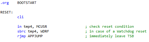
So I opened up tsb_tinymega.asm which is where the hex file is generated from and took at look at the WDT routine, they just detect if a watchdog reset has occurred and then jump to our application, the compiled ASM code comes to 510 bytes.
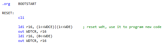
Luckily for us Atmel has an example to turn off the WDT in ASM, 4 instructions so we’ll replace their code with the one provided, compiled and it came to 512 bytes, just fits. All we do is turn off the WDT and continue on, just like it would when you plug in power for the first time.
#define RESET_AVR '*'
#define RESET_VALUE 0x7E5E1

// Reset the AVR if it matches the number
else if (receivedChar == RESET_AVR) {
	usart_read_chars();
	uint32_t resetValue = strtol(receivedBuffer, NULL, 16);
	if (resetValue == RESET_VALUE) {
		// Clear watchdog flag
		MCUCSR &= ~(1<<WDRF);

		// Start timed sequence
		WDTCR = (1<<WDCE) | (1<<WDE);

		// Reset in 250 ms
		WDTCR = (1<<WDP2) | (1<<WDE);

		// Wait for reset
		_delay_loop_2(65535);
	}
}
Now we can make a little program (which I called GBxCart RW WDT Reset) to read the COM port as an argument and send a special command which in the AVR will activate the WDT and reset itself. Above is the AVR code to start the watchdog and reset in 250ms when the reset command is received.
The WDT Reset program (not shown) closes the COM port, waits 300ms, exits so that we can call TSB right after to update the firmware. We wrap this all up into a .bat file and let the user enter the COM port number and it will then update the firmware.
32KB Gameboy Flash Cart support
It was about time to try out re-flashing a Gameboy flash cart and I was able to pick one up at a low cost. I didn’t think it should be too complicated seeing as most flash devices use similar write cycles plus there was no MBC so it would just be a direct connection to the flash. The cart arrived, it used an AMD 1Mbit Flash (AM29F010B) which has CE as A15 and WE as the audio pin on the cart as expected.
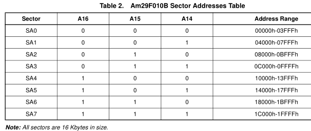
For the AM29F010B, the sector size is 16KB so since we have a 1Mbit flash, it best to just use sector erase as we would only need to erase 2 sectors. We will need to shift the sector to erase by 14 bits so we start off at A14 (SA1 would be 1 << 14).
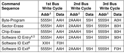
To program and erase, it’s pretty similar to the other flash devices except it only uses 12 bits for the commands where as some others uses 16 bits.
void audio_flash_write_bus_cycle(uint16_t address, uint8_t data) {
	GBA_DDR_RAM_DATA7_0 = 0xFF; // Set data pins as outputs
	set_16bit_address(address);
	GBA_PORT_RAM_DATA7_0 = data;

	audioPin_low; // WE low
	asm volatile("nop");
	asm volatile("nop");
	asm volatile("nop");
	audioPin_high; // WE high
}
To write a command/data to the flash, we do something similar to reading/writing to the ROM/RAM, set the address up, the data byte and then just pulse the audio pin.
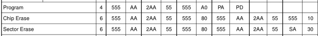
fw3_gb_flash_write_address_byte(0x555, 0xAA);
fw3_gb_flash_write_address_byte(0x2AA, 0x55);
fw3_gb_flash_write_address_byte(0x555, 0x80);
fw3_gb_flash_write_address_byte(0x555, 0xAA);
fw3_gb_flash_write_address_byte(0x2AA, 0x55);
fw3_gb_flash_write_address_byte(sector << 14, 0x30);
To erase a sector, I did it on the software side which calls the above function to write the address/bytes we would like.
void audio_flash_write_byte(uint16_t address, uint8_t data) {
	audio_flash_write_bus_cycle(0x555, 0xAA);
	audio_flash_write_bus_cycle(0x2AA, 0x55);
	audio_flash_write_bus_cycle(0x555, 0xA0);
	audio_flash_write_bus_cycle(address, data);
	_delay_us(20); // Wait byte program time
}
We can just wrap everything up in a function on the firmware so it does the write bus cycles for us and then programs the byte.
2MB BV5 Gameboy Flash Cart MB5 support
After supporting the first flash cart it was time to try a larger sized one which had MBC5. The cart arrived and it was a “BV5” one, I couldn’t read the label of the flash too well, it was a Spansion 2xxx016M10T. I started looking up BV5 carts and came along to the AMD 16Mbit Flash (AM29DL163DB).
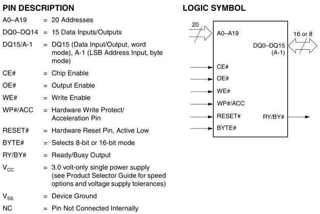
I started checking my flash chip pin out compared to the AMD one and for the most part it seemed to match up but there were some things that weren’t the same and others worth mentioning.
CE on the cart pin didn’t go to the Flash or the SRAM
A0 = DQ15/A-1 on the chip
A1 = A0 on the chip
A14 = Went to the MBC
A15 = CE
D0 = DQ1
D1 = DQ0
Byte# to GND
Reset# and WP# to VCC
(Other pins not mentioned would likely go to the MBC)
Firstly they have the Byte# to ground which means that 8 bit data mode is selected, the fact that this chip can do 16 bit data would make it suitable for GBA carts. As Byte# is going to ground, they need 1 more address line as 2 ^ 20 = 1Mbit x 8bit = 8Mbit so this is where the A-1 line comes in (A minus 1, threw me off a bit). In 8 bit mode, A0 would be A-1, A1 would be A0, A2 would be A1, etc.
Secondly they have the data pins D0 and D1 swapped around, could this be to protect against unwanted writing to the Flash? This means that the data bytes we send to flash to control it will need to have data bits 0 and 1 swapped however the data for the ROM can remain as is and no bit swapping is required as you write the byte and it would read it out the same.
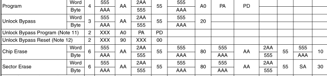
Programming bytes or erasing the chip/sectors can be done as above, since we are 8 bit mode, we use the Byte row.
void bv5_flash_write_bus_cycle(uint16_t address, uint8_t data) {
	GBA_DDR_RAM_DATA7_0 = 0xFF; // Set data pins as outputs
	set_16bit_address(address);
	GBA_PORT_RAM_DATA7_0 = data;

	wrPin_low;
	asm volatile("nop");
	asm volatile("nop");
	asm volatile("nop");
	wrPin_high;
}
Since CE will always be low, it’s similar as before except that we just pulse the WR pin.
void bv5_flash_write_byte(uint16_t address, uint8_t data) {
	bv5_flash_write_bus_cycle(0xAAA, 0xA9);
	bv5_flash_write_bus_cycle(0x555, 0x56);
	bv5_flash_write_bus_cycle(0xAAA, 0xA0);
	bv5_flash_write_bus_cycle(address, data);
	_delay_us(20); // Wait byte program time
}
Here’s what a program write cycle would look like, notice that the first line should have the data byte 0xAA but since bit 0 and 1 are swapped we have A9.
I was playing around with sector erases and switching banks but nothing that I could do would make it erase the second sector, only the first sector which was 4Kbytes would be erased.
// Chip erase (data byte's bit 0 & 1 are swapped for chip commands as BV5 D0 & D1 lines are swapped)
gb_bv5_flash_write_address_byte(0xAAA, 0xA9);
gb_bv5_flash_write_address_byte(0x555, 0x56);
gb_bv5_flash_write_address_byte(0xAAA, 0x80);
gb_bv5_flash_write_address_byte(0xAAA, 0xA9);
gb_bv5_flash_write_address_byte(0x555, 0x56);
gb_bv5_flash_write_address_byte(0xAAA, 0x10);

// Wait for first byte to be 0xFF
readBuffer[0] = 0;
while (readBuffer[0] != 0xFF) {
...
The only other thing we can do is use a chip erase which takes about 25-30 seconds or so, we just wait for the first byte to be 0xFF to know the erase has been completed.
currAddr = 0x0000;
for (uint16_t bank = 1; bank < romBanks; bank++) {
	if (bank > 1) { currAddr = 0x4000; }

	set_number(currAddr, SET_START_ADDRESS); // Set start address

	while (currAddr < endAddr) {
		if (currAddr == 0x4000) { // Switch banks here just before the next bank, not any time sooner
			set_bank(0x2100, bank);
		}

		set_mode(GB_FLASH_WRITE_64BYTE);
		com_write_bytes_from_file(GB_BV5_FLASH_WRITE, romFile, 64);
		...
	}
}
Before performing any byte programming, I found that I had to read the ROM a little bit (it could be that it has to set other things up). To write to the next sector, we have to switch banks but only just before we want to write to that sector and we start the write at 0x4000h until 0x8000h then go back to 0x4000h like normal. For example, to write to 0x8000h in the ROM, you would switch banks to 2 and begin the write at 0x4000h.
And that pretty much covers the major things that changed.


Amazing job. Are you planning to release an update schematic? Thank you 🙂
Yep, here is the new schematic for the v1.3 version released late last year:
That’s great!
Thank you a lot
I really need to say thank you, I easely achieved to make my own personal version of the reader (I’m using the ATmega32, it works flawlessly), I’m really satisfied!
Looking forward to buy your last GBA flashcart with save support.
Keep on going, you’re awesome I love your articles
Nice, good to hear it works! And thank you 🙂
Hey, quick question. I’m trying to make my own version of this for a school project but i cant find the footprint for the cart slot anywhere. Do you have the measurements for this?
Thanks 🙂