I have a couple of nRF24 devices around the house like the doorbell, front door camera, the single receiver for both and I might look to expand that list in the future but re-programming the receiver when you would like it to handle a new device or perform an additional action can take a while plus the time testing that everything works.
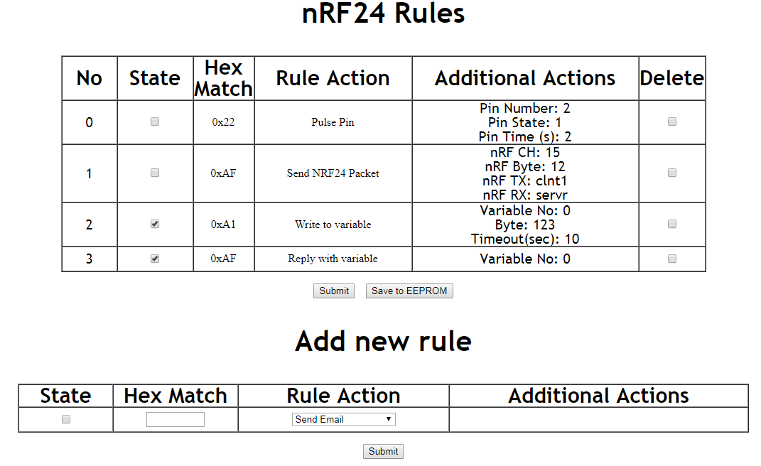
So I thought, why not make an ESP8266 for a web interface where we can store rules and have it connected to the nRF24 to receive incoming packets, it’s similar to IFTTT but all local. The rules would all be based on a single byte packet it would receive, we could have the rules active or not, with rule actions such as sending an email, pulsing a pin for a certain amount of time, sending an nRF packet, writing data to a common variable (with a timeout when it’s reset) and reply back with that variable. We can have a button to save everything to the EEPROM (emulated on flash) and read it all back if the ESP8266 is power cycled.
Some quick use cases:
– Doorbell is pressed, you could either have it pulse the buzzer locally for a second or two and you could also have a remote buzzer anywhere else so it sends a packet to have that buzzer go off too.
– I’m thinking about adding a small sensor to the mailbox, so if it’s moved, it would send a packet, we could have it write data to a variable. Add a battery powered sensor anywhere around the house with either a buzzer or LED, to check in every few seconds and read that variable back so if it changes to a 1, the buzzer or LED goes off for a little while.
We can start off modifying the LiPo Battery Storage Monitor project as it’s got nRF24 support already working as well as a ~1 second interrupt acting as a timer.
uint8_t nrfVars[10] = {0, 0, 0, 0, 0, 0, 0, 0, 0, 0}; // Common vars which rules can read/write to
uint8_t nrfVarsTimeout[10] = {0, 0, 0, 0, 0, 0, 0, 0, 0, 0}; // If there is a time out when the value needs to be cleared

// Rules structure
#define MAX_RULES 30
struct Rule {
  uint8_t state;
  uint8_t dataMatch;
  uint8_t ruleAction;

  uint8_t ruleActionExtra1;
  uint8_t ruleActionExtra2;
  uint8_t ruleActionExtra3;

  char ruleActionExtra4[20]; // Email to or nRF TX
  char ruleActionExtra5[20]; // Email subject or nRF RX
};
Rule ruleList[MAX_RULES];
uint8_t ruleCount = 0;
Firstly we need to define our data structure, we have an array of 10 bytes to use for our write/read variables function as well as the timeout counter for those. We then have the state of the rule 0 or 1, the incoming byte to match on, the ruleAction is just a number between 0 to 4 and generic variables and character arrays which could be used by any rule.
Now that we have the structure, the rest is mostly simple and we can test every rule to make sure it works so we don’t have to worry about it again.
// POST: New rule
if (server.hasArg("bytematch")) {
  ruleList[ruleCount].state = server.arg("state").toInt();
  char byteConvertStr[10];
  strncpy(byteConvertStr, server.arg("bytematch").c_str(), 5);
  ruleList[ruleCount].dataMatch = strtoul(byteConvertStr, NULL, 16);
  ruleList[ruleCount].ruleAction = server.arg("action").toInt();

  if (ruleList[ruleCount].ruleAction == 0) { // Send email
    strncpy(ruleList[ruleCount].ruleActionExtra4, server.arg("email-to").c_str(), 20);
    strncpy(ruleList[ruleCount].ruleActionExtra5, server.arg("email-subject").c_str(),
  }
...
We have the new rule POST, we just store all the input in the data structure according to the rule action.
// POST: Update / Delete rule
if (server.hasArg("submit-delete")) {
  uint8_t ruleDelete = server.arg("delete").toInt();

  if (ruleDelete >= 1) {
    ruleDelete--;
    ruleList[ruleDelete].state = 0;
    ...

    // Re-arrange rules
    for (uint8_t x = ruleDelete; x < ruleCount; x++) {
      ruleList[x].state = ruleList[x+1].state;
      ...
    }
    ruleCount--;
  }

  // Update states
  for (uint8_t x = 0; x < ruleCount; x++) {
    if (server.arg("state" + (String) x).toInt() == 1) {
      ruleList[x].state = 1;
    }
    else {
      ruleList[x].state = 0;
    }
  }
}
We may have to edit the rule to disable/enable it or delete it completely. When we delete a rule, we loop through all the rules starting from the rule deleted to copy them all down by one.
// POST: Save EEPROM
if (server.hasArg("save-eeprom")) {
  uint16_t eepromCounter = 0;
  for (uint8_t x = 0; x < ruleCount; x++) {
    if (ruleList[x].dataMatch >= 1) { // 46 bytes per rule
      EEPROM.write(eepromCounter++, ruleList[x].state);
      ...
      for (uint8_t c = 0; c < 20; c++) {
        EEPROM.write(eepromCounter++, ruleList[x].ruleActionExtra4);
      }
      ...
    }
    else {
      break;
    }
  }
  EEPROM.commit();
}
When we wish to save the rules, we can save them to the EEPROM which the ESP8266 doesn’t have but emulates it through the flash which is why we need to commit the EEPROM after we are finished writing to it. We’ve got 4096 bytes which is plenty for us, our structure is always going to be the same at 46 bytes each rule.
// Load rules from EEPROM
EEPROM.begin(4096);

uint16_t eepromCounter = 0;
for (uint8_t x = 0; x < MAX_RULES; x++) {
 uint8_t dataCheck = EEPROM.read(eepromCounter + 1);
 uint8_t ruleActionCheck = EEPROM.read(eepromCounter + 2);

 if (dataCheck >= 1 && dataCheck != 255 && ruleActionCheck <= 4) { // 46 bytes per rule
	ruleList[x].state = EEPROM.read(eepromCounter++);
	ruleList[x].dataMatch = EEPROM.read(eepromCounter++);
	...
	ruleCount++;
 }
 else {
	break;
 }
}
For loading from the EEPROM at start up, we just check if the DataByte is more than 1 and not 255 (blank), and if the rule action checks out, we load everything back again, easy.
// Check if we have a packet waiting
if (mirf_status() & (1<<RX_DR)) {
	mirf_CSN_lo; // Pull down chip select
	SPI.transfer(R_RX_PAYLOAD); // Send cmd to read rx payload
	dataIn = SPI.transfer(0x00); // Read payload
	...

	// Process packet
	for (uint8_t x = 0; x < MAX_RULES; x++) {
		if (ruleList[x].state == 1 && ruleList[x].dataMatch == dataIn) { // Rule enabled and data matched?
			if (ruleList[x].ruleAction == 0) { // Send email
				...
			}
			else if (ruleList[x].ruleAction == 1) { // Pulse Pin
				digitalWrite (ruleList[x].ruleActionExtra1, ruleList[x].ruleActionExtra2);
				ruleList[x].ruleActionExtra4[0] = ruleList[x].ruleActionExtra3 + 1; // Let the 1 second timer handle setting the pin back
				Serial.println("Pulsed pin");
			}
For the main loop, we just check if a packet is waiting, loop all the rules, check if they are active, if the data byte matches and then the rule action to take.
// Decrease timeout of variables
void timer0_ISR (void) {
	timer0_write(ESP.getCycleCount() + 80000000L); // 80MHz = 1 sec

	// Deincrement common variables timeouts
	for (uint8_t x = 0; x < 10; x++) {
		if (nrfVarsTimeout[x] <= 250) {
			nrfVarsTimeout[x]--;
		}
		else if (nrfVarsTimeout[x] == 0) { // Clear value as timed out
			nrfVars[x] = 0;
		}
	}

	// Check for delay timeouts for pulse pin
	for (uint8_t x = 0; x < MAX_RULES; x++) {
		if (ruleList[x].state == 1 && ruleList[x].ruleAction == 1) {
			if (ruleList[x].ruleActionExtra4[0] >= 1) {
				ruleList[x].ruleActionExtra4[0]--;
				if (ruleList[x].ruleActionExtra4[0] == 0) {
					digitalWrite (ruleList[x].ruleActionExtra1, !ruleList[x].ruleActionExtra2); // Set pin back
				}
			}
		}
	}
}
For example, the pulse pin rule, we write the pin state and then store the timeout value in one of the extra variables, we’ll be letting the timer handle the delay and switch the pin back to how it was, this is so we don’t get locked up waiting for the delay, same thing goes for the common variables.
Download esp8266_nrf_rules_server_v1
And that’s about all there is to it, now you just need to write down the nRF TX/RX address of each device you put up with their specific byte to perform an action and you can have the rule do that. The only downside is that for an nRF device/sensor to transmit an event to our rule server (say doorbell pressed), it needs to have fixed a TX/RX address and it’s own unique byte on our rule server, there are over 200 possible combinations so I think that should be fine, don’t expect to have more than 10-20 sensors.


