
Wouldn’t it be nice to know it you have mail? I think it’s a good idea and had it on my to do list for a while. Our letterbox looks similar to the one above, you can place small items on the top, in the letter slot or open it up from the back.
At first I thought we could do this with a vibration switch however upon testing the switch it looks like it needs a fast motion in order to activate. Another option is a reed switch on the top part so if the mailbox is opened, it will detect that, but would leave letters undetected. And yet another option, is a light sensor placed inside the mailbox but also results in the same problem.
So one of our last options is to use an accelerometer to detect the slightest touch of the mailbox, most mailboxes are pretty rigid but ours has a tiny bit of moment to it, we can’t really put the device we would make in the letterbox itself as the RF would mostly be blocked so it would have to be placed outside. As usual, I’ll be using an ATtiny84 with the nRF24 to simply send a packet when the interrupt occurs.
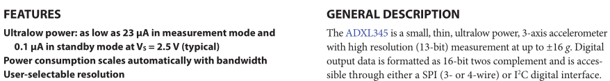
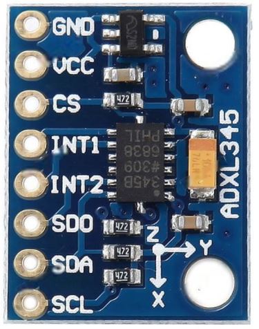
The accelerometer I’m looking at as you can tell by the title is the ADXL345 which has 2 interrupts available for single tap, double tap, activity, etc, and current consumption looks to be pretty low. It supports I2C or SPI, we’ll be using 4-wire SPI.
So I tried the SparkFun ADXL345 example which worked well, they have all the interrupts available so all I need to do is take everything I don’t need out, convert it to C and try out the low power modes. Note that the ADXL345 is a 3.3V device so you will need a logic level converter if using it with a 5V Arduino.
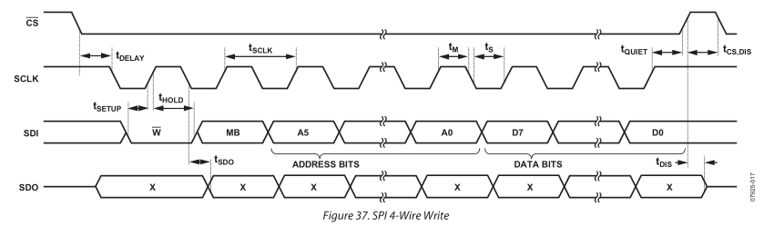
Another thing we need to keep mind of is that that the ADXL345 is a negative edge clocked device which means CLK starts off high where as the nRF24 is positive edge clocked device (CLK starts low), so I went the bit-bang method for both devices so they can use the same pins except for CE.
Code with datasheet references
Let’s jump into the code to setup the device.
adxl_spi_write(ADXL345_POWER_CTL, 0);  // Wakeup
adxl_spi_write(ADXL345_DATA_FORMAT, 0);
adxl_spi_write(ADXL345_BW_RATE, 0x17); // Bandwidth and low power

// Activity / Inactivity
adxl_spi_write(ADXL345_ACT_INACT_CTL, 0x44); // X - axis to apply to (DC)
adxl_spi_write(ADXL345_THRESH_ACT, 5); // Threshold
adxl_spi_write(ADXL345_THRESH_INACT, 5); // Threshold
adxl_spi_write(ADXL345_TIME_INACT, 1); // Time

// Enable interrupt activity
adxl_spi_write(ADXL345_INT_ENABLE, 0x18);

// Enable sleep mode
adxl_spi_write(ADXL345_POWER_CTL, 0x30);
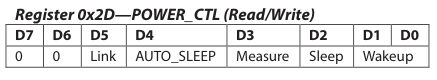
First we wake up the device, just in case any of the bits in the power control register are set, we set to 0.
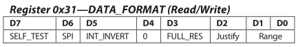
We set range to be 2g as it’s the most sensitive and 4-wire SPI.
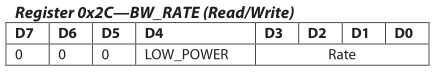
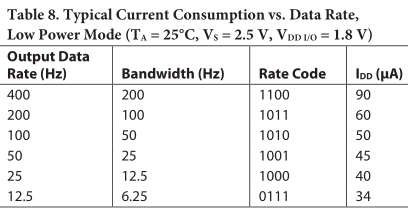
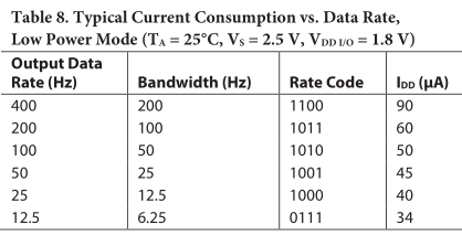
Output data rate set is 12.5Hz with the low power bit set, this will give us the best data rate for the lowest current consumption.
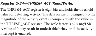
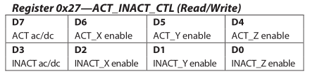
The threshold activity and inactivity are set along with which axis these should apply to, there is a time in seconds to say when inactivity should register. At 2g, setting the threshold to 2 made it activate if I blew some air on it, so I set it to 5 and it seems good there, I might lower it to 3 or 4 as it will be in an enclosure.
You also have to account for gravity depending on how the device will be positioned, if it’s flat you can use the X and Y axis but not Z. You could use Z but you would have to increase the threshold way higher and it would remove your low vibration sensing as all axis shares the same threshold. You can check this out by slowly tilting the device, you will see it blinks once for activity but doesn’t blink again for inactivity until you tilt it back as it thinks it’s still active. It’s more apparent if you switch to measure mode with only activity on, the LED stays on.
adxl_spi_write(ADXL345_ACT_INACT_CTL, 0xCC); // X-axis to apply to (AC)
The solution to this is to AC couple the axis, so it compares the last movement to the current one and not to what is the zero movement point for each axis.
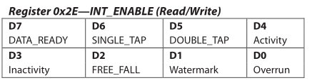
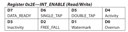
We enable the activity and inactivity interrupt.
The reason we need to enable both activity and inactivity interrupt is because we will set the device to auto sleep, so once it detects movement, it will wait until the inactivity timeout before going back to sleep, this should save battery life.
adxl_spi_read(0x32); // Read x, y, z to clear
adxl_spi_read(0x33);
adxl_spi_read(0x34);
adxl_spi_read(0x35);
adxl_spi_read(0x36);
adxl_spi_read(0x37);
adxl_spi_read(ADXL345_INT_SOURCE); // Read interrupt source to clear
After setup, once the AXDL INT1 pin goes high, we will just need to read out x, y, z and read the interrupt source.
Testing
I checked for the power consumption when the device was powered on but we hadn’t set it up, it came to 1mA a bit high. I ended up taking out all the resistors which were there (for I2C or current limiting), removed the 3.3V on board voltage regulate and then it dropped to 0.3uA, good.
There is a measure mode which constantly does measurements and I left it at the default 100Hz rate, it came to 180uA. Then I tried running the code we setup as above, it didn’t work the device never came out of sleep mode. I tried to set measure mode as well as link and autosleep, I got 45uA, it works but not as low as it should be. I doubled checked the datasheet and was doing as they said. I tried changing the rate, it made no difference to the current consumption.
adxl_spi_write(ADXL345_POWER_CTL, 0); // Wakeup
adxl_spi_write(ADXL345_DATA_FORMAT, 0); // 2g and 4-wire SPI

adxl_spi_write(ADXL345_BW_RATE, 0x17); // Low Power Mode with 12.5 Hz data rate
adxl_spi_write(ADXL345_ACT_INACT_CTL, 0xF0); // Set activity on x, y, z (AC)
adxl_spi_write(ADXL345_THRESH_ACT, 5); // Activity Threshold

adxl_spi_write(ADXL345_INT_ENABLE, 0x10); // Enable interrupt on activity
adxl_spi_write(ADXL345_POWER_CTL, 0x08); // Measurement mode
I went back to measure mode, took off the inactivity interrupt and could see that changing the rate there did affect current consumption, dropped it down to 12.5Hz like before, still got 45uA, very odd, at least now we only have the activity interrupt, maybe I wanted too much from the ADXL345.
The only thing the ATtiny84 does once it receives an interrupt is send a single byte packet and now the nRF Rules Server can do what ever we want with it. Download nRF_Letterbox_TX_v1.0
Putting it all together
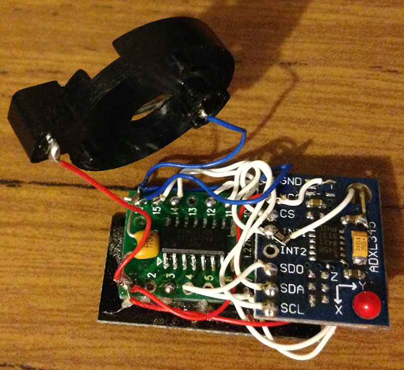
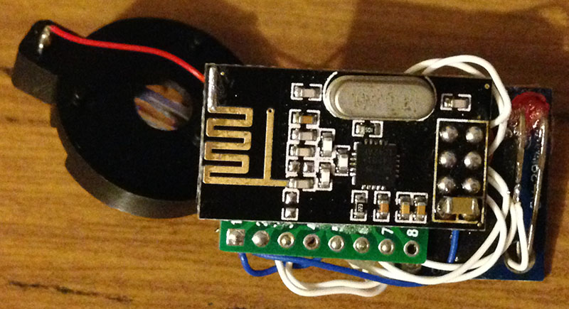
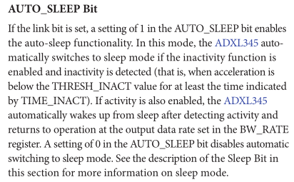
I was able to grab an nRF24 module, glue it to an SOIC adapter and tape the ADXL345 to it, doesn’t look pretty but it works, powered with a 3V coin cell, it should last 170 days or so, then I might switch it over to a small LiPo battery. Putting a tiny solar panel on the mailbox would be nice but might give away that some electronics is hooked up to it.
A quick 3D print of a case later and we’re ready to go. Now I just need to paint it to match the mailbox and test it a bit, initial tests suggest that it should work well.


