I’ve playing around with DC-DC step down converters but haven’t really had a need for step-up converters until recently. I have a portable device which requires ~12V 100mA so I’ve been powering it with 4x 3.3V LiFePO4 14500 batteries so it would be nice to reduce the weight a little bit by using a step-up converter knowing that the run-time will decrease.
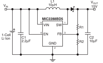
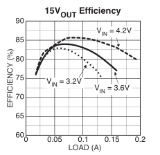
So I went looking around for some chips and found the Micrel MIC2288 for 90c which supports 2.5V to 10V input, up to 34V output and 1A switch current. A quick look at the datasheet and the BOM looks good and the efficiency chart seems to say it can do at least 100mA at 3.2V so it’s looking good.
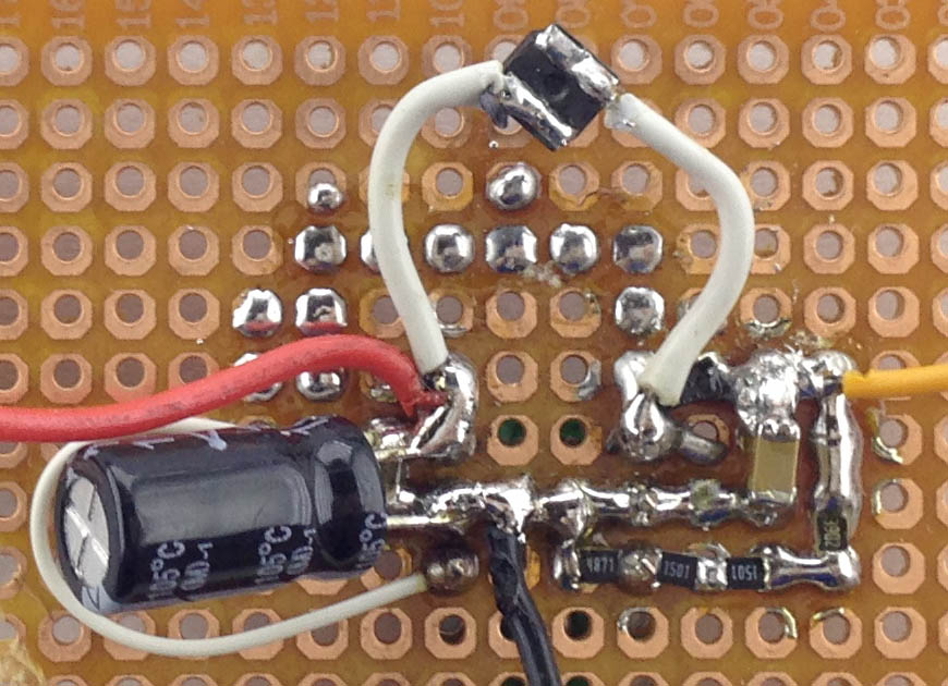
So I built it all up, used a 15uH inductor instead of the 10uH they showed. On the output I got 11.8V so all seemed well, put a 1.5K resistor (8mA load) which was fine, then I tried 330 ohm (36mA load) and that’s when I saw the voltage drop to 9V or so on the multimeter, strange plus I heard some sounds coming from the circuit. I started bumping up the voltage from 3.3V and once I hit 5.2V the output seemed to go back to 11.8V. I went back the other way, once I hit 2.3V to 2.8V it started working normally again. No components were getting hot.
I swapped the inductor for a 22uH one, same issue. I was about to measure the voltage across the Schottky diode when I touched the first lead to the SW (point where the inductor and Schottky diode meet) and the sound went away and the voltage went back to 11.8V. The current draw at 3.3V input was 150mA and it stayed the same when touching the SW pin. I swapped out the Schottky diode for a larger one but there was no change and touching the SW pin didn’t work this time.
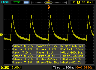
Over to the scope to see what’s going on. We can see with the 36mA load it’s 7Vpp so the multimeter wasn’t too far off (All tests done using ground lead, so actual noise would be better). Without any load it was around 100mVpp.
I read over the datasheet and they mentioned that if you increased the inductor size, you have to also increase the output capacitance, could a 10uH increase in inductance cause what we were seeing?
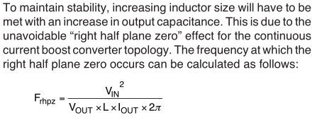
Apparently it did, I dropped the inductor to 4.7uH and the issues went away, now it’s 340mVpp with the 36mA load, not great but much better.
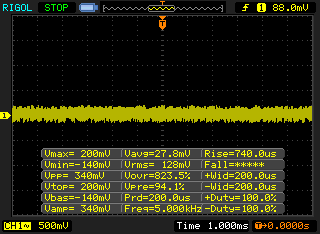
When adding another 220 ohm resistor (90mA total load), it rose to 1.28Vpp, not looking good.
I tried switching to the only 10uH inductor I had (large, rated for 4A) but the voltage dropped again like before, so it seems only 4.7uH inductors work best. I added another 10uF capacitor when the 36mA load was applied and it dropped from 340mVpp to 260mVpp.
When the input voltage was set to 3.3V with a 12V 90mA load, it drew 436mA, quite a bit so a single LiFePO4 won’t be able to handle this load without a large voltage drop. When at 6.6V input, it drew 193mA so I might have to use 2 batteries in the end.
So the MIC2288 isn’t looking too great so I went looking for another step-up DC-DC.
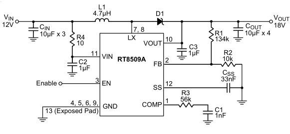
It’s the Richtek RT8509A which was on special for $1.2 (now it’s $4), 2.5V to 14V input, up to 24V output, 4.5A switch current, a bit of a larger BOM count but this chip should be able to handle just about anything.
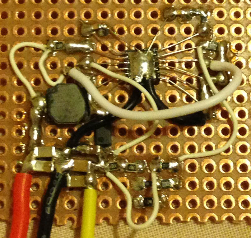
What I didn’t release before ordering was that it’s a WFDN package, this thing will be tricky to solder, so dead bug style it was. I got the output set to 12.7V and with the 330 ohm it’s a 38mA load, tested the voltage range from 2.8V to 7V had no problems at all.
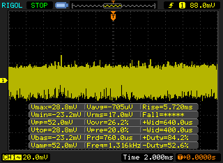
Lets check the RT8509A performance, with no load it’s 52mVpp, not bad.
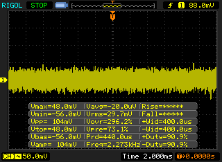
With 330 ohm load it’s 104mVpp and adding another 220 ohm load it stayed around the same noise, so the RT8509A is definitely the winner in terms of noise performance but it’s kind of an unfair comparison ($4 chip vs 90c chip). So I will go ahead and use the RT8509A for the device.
I’ve checked around a bit for slightly better chips than the MIC2288 at a lower price than what the RT8509A really costs. There is a MIC2253 for $1.46 that has 3.5A min switch current, 2.5-10V input, up to 30V output and uses a slightly larger BOM than the MIC2288. Maybe it’s still worth trying another SOT-23-5 device to see if I have better luck with it, the LMR64010 looks good for $1.1, 2.7-14V input and up to 40V output.


Hey Alex,
I really appreciated your post, it shed some light into what I was doing with MIC2288. But I think you should update it.
I’ve tried various fixes for my MIC2288 test board, and nothing seemed to work. I only got up to ~10V without load and ~4.8V with load. Until I replaced the standard diode with a SCHOTTKY diode and reduced the output capacitor to 4.7uF/50V. The resistor ratio is 24.3:1, and I’m getting about 30.2V output with a ~10mA load.
PS: check this out: https://www.youtube.com/watch?v=bXEyCf1P0UU
Cheers,
Paul
Hi Paul,
The diodes I would have been using would have been Schottky diodes, I’ll update the post to reflect this. Just curious, what’s your input voltage?
I use a 5V USB-powered TP4056 lithium charger to charge up a lithium battery / supercapacitor to 3.60~4.25V. If I disconnect the battery/supercap I usually get a stable 20V output from 2.1~2.4V input (using 2x22uF output capacitors on the charger’s battery pin).