I know this sort of project has been done before but nevertheless it’s still an interesting project to try and put your own spin on it. The idea is to have an ESP8266 which can press/hold the power button and might as well have it also read the power LED state, you could also wire up the reset button if you wanted to, it’s a good concept for servers (or PCs) which don’t have a remote management and you need something basic.
(sneak peak of prototype)
One option might be using the 5V standby power which most power supplies provide when the PC is off. Some PCs might have 5V standby available in the BIOS, the keyboard and mouse might stay on, maybe you could find some pins on the mainboard but perhaps some mainboards might not have it? Let’s just avoid it all, I’m thinking I could have the ESP8266 powered off a 3.3V LiFePo4 battery in a small little case which when the PC is on, it will recharge itself via USB, this way we don’t need the PC to be on or have the ESP8266 powered via a mains adapter.
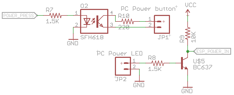
For the circuit, we can sense the power LED, it will have a voltage drop out say 2-3V with the LED but could have 5V if the LED isn’t connected for whatever reason, we’ll just use a NPN to switch 3.3V on or off to our input pin. The power switch we can use an opto-isolator to turn it on or off which can be inline with the power button. We can also integrate the USB LiFePO4 charger into this project to charge the battery.
That’s pretty much all there is to the hardware, now for the software which is where it’s all at. We want to make it as simple as possible to setup without needing any port forwarding on the client’s end, so the design is to have the ESP8266 reach out to a server to fetch a command over HTTPs. We don’t want the ESP8266 to be awake all the time otherwise the battery won’t last long so we’ll utilise the deep sleep function and say wake up once every 5-10 minutes.
// If button is held when booting or if setup byte in EEPROM is 255, boot AP mode
uint8_t deviceSetup = EEPROM.read(EEPROM_LOCATION_DEVICE_SETUP);
if (digitalRead(setupPin) == 1 || deviceSetup != 1) {
	...
	WiFi.mode(WIFI_AP);
	WiFi.hostname("RemotePowerCycler");
	WiFi.softAP("RemotePowerCycler-AP", "1928472742"); // Change this for every device

	randomSeed(analogRead(A0)); // Generate random device ID
	deviceID = random(0, 2147483647);
	...
}
Like I’ve done before, if the device hasn’t been setup before or the setup button is held at boot, the ESP8266 becomes an AP with a password we’ve preset. Because we need to communicate to our server, we don’t really want to put in any client names, computer names, etc, so we use the analog A0 pin (left disconnected) to generate a random device ID, this is all the server will see when we are checking in.
zxc
Once the Wifi information is entered and saved, we write this to the EEPROM and boot as normal. Ideally when the device is setup, we make a note of the device ID and add it on the server to accept it’s requests, there we can add client info, computer name, etc, so only the server can see this information.
// Use WiFiClientSecure class to create TLS connection
WiFiClientSecure client;
Serial.print("Connecting to server... ");
if (client.connect(serverHost, httpsPort)) {
	 Serial.println("Ok");
	 uint8_t powerStatus = !digitalRead(powerLedPin); // Read power pin

	 String url = (String) "/project/rpcycler/checkin.php?d=" + deviceID + "&p=" + powerStatus;
	 client.print(String("GET ") + url + " HTTP/1.1\r\n" +
		 "Host: " + serverHost + "\r\n" +
		 "User-Agent: ESP8266\r\n" +
		 "Connection: close\r\n\r\n");

	 Serial.println("Request sent");
	 while (client.connected()) {
  	 	 String line = client.readStringUntil('\n');
  		 if (line == "\r") {
	 	 	 Serial.println("Headers received");
		  	 break;
  	 	 }
	 }

	 // Read the data (faster than .readString)
	 int readChar = 0;
	 char responseChars[10];
	 uint8_t responseCounter = 0;
	 while (responseCounter < 9) {
  	 	 readChar = client.read();
  	 	 if (readChar != -1) {
		 	  responseChars[responseCounter] = (char) readChar;
		 	  responseCounter++;
  	 }
  	 else {
		  break;
  	 }
After loading the EEPROM Wifi information and booting up, we can use the WiFiClientSecure client class to connect to our server via SSL and send our device ID so the server can respond with the action to take, I thought it would be a good idea to send through the computer’s power state.
For some reason when testing the readStringUntil for the actual data reply, it would take at least 5-10 seconds for it to finish, the reading headers the part worked fine. I had to just use client.read to only read the first 8 bytes of data as the server’s replies will be very short and that worked quickly.
// Process action
if (responseChars[0] == CMD_POWER_BUTTON_PRESS) {
	commandReceived = 1;
	Serial.println("Power button press");

	digitalWrite(powerButtonPin, 1);
	delay(500);
	digitalWrite(powerButtonPin, 0);
}
else if (responseChars[0] == CMD_POWER_BUTTON_HOLD) {
	commandReceived = 1;
	uint8_t holdTime = strtoul(&responseChars[1], NULL, 10);

	Serial.print("Power button hold for ");
	Serial.print(holdTime);
	Serial.println(" seconds");

	Serial.print("Holding down power button... ");
	digitalWrite(powerButtonPin, 1);
	delay(holdTime * 1000);
	digitalWrite(powerButtonPin, 0);
	Serial.println("Done");
}
The servers reply will just be “0” for no action, “p” to press the power button and “h10” to hold the power button for 10 seconds. Once the client checks in with the server, the server changes the current action back to “0”. The actions the ESP8266 needs to take is pretty simple, just set the output high and then low again.
// Don't go to sleep for too long if a command was received
if (commandReceived == 1) {
	Serial.println("Going to sleep for 20s");
	ESP.deepSleep(20 * 1000000);
}
else {
	Serial.println("Going to sleep for 5 minutes");
	ESP.deepSleep(300 * 1000000);
}
Once the command has been processed we can go to deep sleep. It’s probably a good idea if a command was recently processed that we don’t sleep for too long just in case we want to do another action quicker, so we only sleep for 20 seconds otherwise we sleep for 5 minutes.
I did have a few issues with the deep sleep command at first, basically when the sleep is over it just reboots the ESP8266. When it was booting, I was receiving serial messages such as “ets Jan 8 2013,rst cause:5, boot mode:(3,5) ets_main.c”. Eventually I tracked it down to having RST and GPIO16 tied to VCC directly, connecting GPIO16 and RST together and using a 1.5K resistor to VCC did the trick.
When the ESP8266 wakes up from deep sleep I did see that output pin to the opto-isolator was going high but gently (I had an LED on the output as a test, it might have been a weak pull up), so I put a 10K resistor to ground on that output pin and it’s all good now.
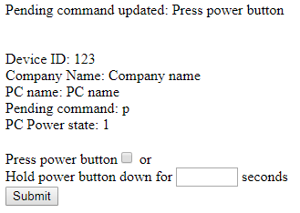
Here’s how the server side looks, pretty basic, it could be as complicated as you wanted it to be. We see the device ID, the pending command and when it last checked in the power was on to the PC; could add in last check-in time.
After a few tests, it all seems to work pretty well as per the video at the start. Download RemotePowerCycler


