In the last part, we looked at 3 DC-DC step down converters, tested their quiescent current and efficiency but none really stood out in both aspects. Near the end, we came up with a solution to which keeps the DC-DC in shutdown and only enables it when the GBA power switch is flicked on. In this part, we’ll continue to test this solution, look at how to detect low battery, order some boards and check the performance.
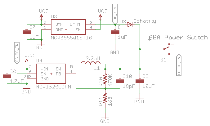
Here’s a schematic to show how the solution works, you can see the LDO’s output goes through the diode and is tied to the DC-DC output. The DC-DC enable pin is tied to the other side of the switch and would normally be off. Once the switch is flicked, the LDO output voltage reaches the DC-DC enable pin and switches the DC-DC on.
Previously I was using a 1.8V LDO I had laying around for testing so I ordered an ultra low quiescent current LDO, the NCP698 which has a quiescent current of 6uA maximum. The 1.8V version was 20c more expensive than the 1.5V variant so I went with the 1.5V one instead as it should still work fine. We don’t want to have too high of a voltage, otherwise the LDO would be powering the GBA instead of the DC-DC.
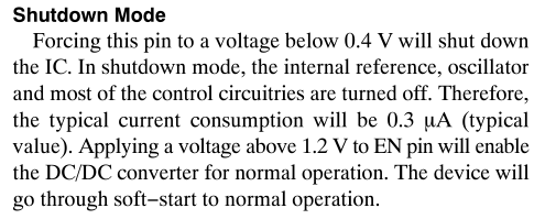
When testing it out, it looked like the output after the diode was 1.33V when the GBA was trying to turn on but the DC-DC wouldn’t turn on, even though the datasheet said the voltage above 1.2V should be enough. I hooked up the LDO voltage to the enable pin directly and it did switch on fine.
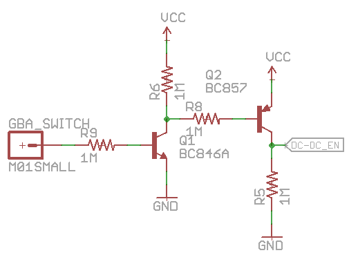
Potentially this could have also happened with the 1.8V variant as well so I wanted to find a way to switch the enable pin to VCC instead of the LDO’s output. After a bit of testing, we can use a NPN with a PNP for our solution, resistors are high value ones so that current consumption is kept low but it only draws current (12uA) when the GBA is on. By default, the NPN is off so the PNP is also off and thus the output is 0. Once the power is flicked on, all we need is at least 0.7V on the NPN so it switches on, the PNP base will then be close to 0V and that will switch on, which means VCC will reach the DC-DC enable pin.
Now we can look at how to detect when the LiPo battery is running low, in my testing a 2000mAh battery with a 500mAh load has used about 1750mAh when it reaches 3.655V and used 2000mAh when at 3.6V. Since it was under quite a lot of load, setting the low voltage to 3.65V might be about right for say 90-95% used.
Edit (a few days after): Actually it looks like my tests were incorrect, I was testing with a 250mAh load, so really it had only used up 1 amp. When repeating the test, the battery used around 1450mAh when it reached 3.3V and it hit 2.93V when it consumed 1675mAh, so best to set it to 3.3V to be safe. It depends on the load, I was testing with a 500mAh load, reduced it to 250mAh once the battery consumed 1000mAh and dropped it to 150mAh when it hit 3.2V.
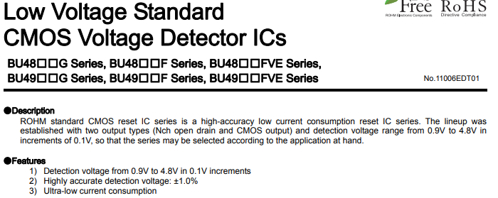
I was recommended voltage supervisor chips which hold the reset line high (or low) at a set voltage, some are fixed and others are adjustable, they have a low 1-2uA current consumption and about a 1% accuracy. The problem is that there don’t seem to be any that are priced decently for 3.65V, they only have 3.6V or 3.7V and the adjustable ones are close to $1 each. The 1% accuracy seems good, but that means for 3.7V it could be 3.663V to 3.737V, kind of a large range.
We might need another solution, either an MCU or an op-amp. I was looking at the ATtiny10, it’s got an 8 bit ADC which might be just enough but I didn’t notice that the ADC reference wasn’t able to be changed to the usual 1.1V internal voltage like you can with the 8 pin variants like the ATtiny13 otherwise the reference as VCC will always change depending on the LiPo battery, so looks like the op-amp might be the go to choice.
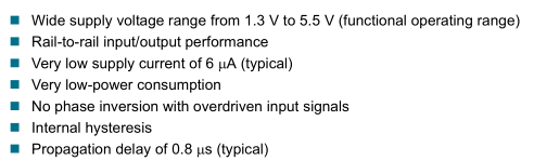
Actually instead of going with an op-amp, I thought I’d try just using a comparator as that’s all I need, it costs less and most have a lower supply current than an op-amp. The one I went with is the NXP NCX2200 which supports 1.3V to 5.5V and has a typical supply current of 6uA so it should work fine.
For the positive side we’ll have a resistor divider for the LiPo but for the negative side, we need a voltage reference. I was starting to think of the best way to do this for the lowest quiescent current but then I forgot we already have the 1.5V LDO, we’ll just use that! We might have to fine tune the resistors divider and test that the accuracy is acceptable for each unit.
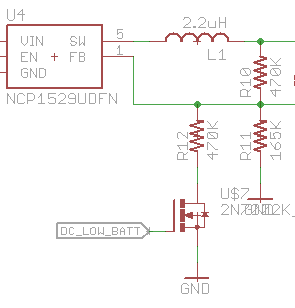
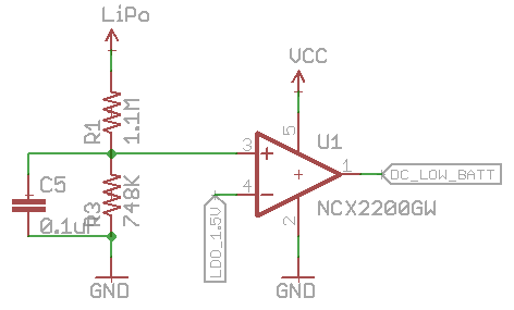
The DC-DC side of the schematic has been updated to reflect adding the comparator. By default the output is high so the mosfet turns on and the 470K resistor is brought into the DC-DC’s resistor divider which is equivalent to putting 122K, so the output goes to 2.9V. Once the LiPo battery is low, the mosfet switches off and we are left with 165K to gives 2.3V output, I might think about making it slightly lower, maybe 2.25V or so.
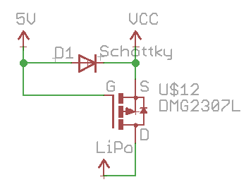
Lastly I thought it might be worth adjusting the voltage switching method. Before I was just using 2 diodes, this time I went with a P mosfet to turn on when 5V isn’t present (not charging) to give us a relatively low voltage drop when powered by the LiPo and just have the diode drop when the 5V is connected (charging).
(It looks a little rough near the top right as I was swapping parts a bit)
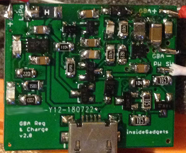
I went ahead with the order for some PCBs, they came within a week and slowly started building each part up, first the DC-DC, adding the transistors for controlling the shutdown pin, the voltage switching, comparator for the low voltage and finally the LiPo charger circuit. Everything seemed to work first go, a surprise for the first PCB, the only thing that needs adjusting is the silkscreen text needs to be bigger and I accidentally put the LiPo battery -/+ silk screen the wrong way around.
At 4.2V, the quiescent current is 11uA so I’m pretty happy about that, it would take about 4 days for it to use 1mA. A quick test of the comparator to see what voltage triggered the low voltage came out to 3.655V, just perfect! It won’t change the LED back to green until it hits !3.7V again so there is some hysteresis built it. Playing around on the power supply going below 3.6V and above 3.7V there wasn’t any glitches when playing a game, same with the automatic voltage switching with the mosfet/diode.
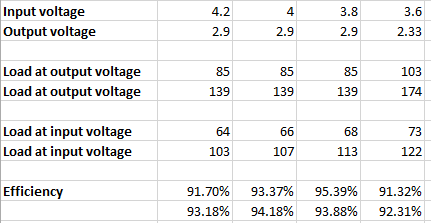
For performance, 2 carts were tested, a regular cart and my flash cart, more than 90% efficient, that’s pretty good.
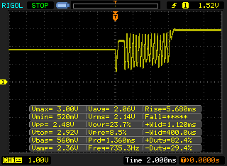
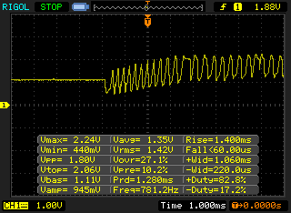
Let’s take out the scope and have a look at how it powers on, it looks a bit odd. I tried powering it off and then on again quickly and the GBA speaker made a little squeak noise, seems like it does that if you don’t leave it powered off for ~15 seconds.
I went back to my prototype and tried it on that, no issues, strange, so I started swapping out parts, adjusting the circuit to bypass the LDO, DC-DC enable, etc but nothing helped. It wasn’t until I used a long lead from the DC-DC output to the GBA when the problem disappeared, I had been using these long leads in the prototype too. I remember about my power supply, I had once experienced issues with long leads from it to my projects before, the fix for those was to put a decent sized electrolytic capacitor.
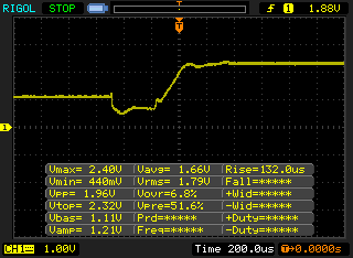
Instead of using the power supply, I just plugged in a LiPo battery and lo and behold, it’s all good now.
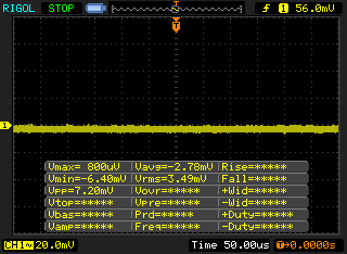
Let’s check the noise, firstly the 1.5V LDO, so little noise that we can’t really pick anything up.
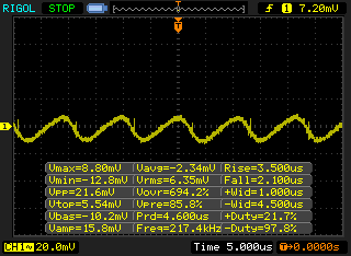
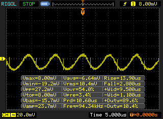
Next up the noise when running a regular cart and my flash cart (which consumes more current), both look pretty good (measuring the GBA battery terminals).
So I think we’re pretty much done here. I’ll just do a bit more testing, order the new PCBs with the silkscreen changes and then it should be ready to go.
Edit 9 Aug: It appears if the LiPo battery gets too low, around 3.0-3.1V, there is a chance the the GBA won’t start up, it will begin to oscillate between switched on/off.
Edit 11 Aug: Seems like it was happening even at 3.2V, if you charged the battery for a second then tried to power on it would happen. It looks like the P mosfet I had from the LiPo to the VCC wasn’t turning on fast enough or wasn’t turning on properly so I’ve added a diode as well and that seems to have solved the issue so far.
There will be a diode drop initially but when the mosfet takes over the diode won’t be conducting anymore. The oscillation will still happen if the battery is low because the DC-DC converter minimum input voltage is 2.7V.


Oh boy, I’m so excited for this!
One question, the board uses MicroUSB or USB C? it would be amazing if it used the newer standard. 🙂
Hi Deses, it’s currently using Micro USB but I might look into USB C as I hear from time to time that some users are looking for that.
My house for instance has completely moved to USB-C, for instance.
It is still not as ubiquitous as MicroUSB, but with the passing of time USB-C is going to be everywhere.
Thank you for considering it! 🙂
Ack, I should have re-read my message, I repeated “for instance” twice! 🙁