Following on from Part 1, we decided to use the ATmega48A instead of using an ATtiny with 2 shift registers and have an example animation working. In this part we’ll look at adding the 32.768KHz crystal, keeping track of the date/time and using PGM to store the LED animations.
We plug in our 32.768KHz crystal to the XTAL/TOSC pins but before we start to use the crystal there is a start up sequence and other considerations which we need to follow that’s shown on the ATtiny48A datasheet.
// Enable the 32.768KHz crystal as a RTC
TIMSK2 = 0; // Disable the Timer/Counter2 interrupts by clearing OCIE2x and TOIE2
ASSR = (1<<AS2); // Select clock source by setting AS2 as appropriate
TCNT2 = 0;// Write new values to TCNT2, OCR2x, and TCCR2x
OCR2A = 0;
OCR2B = 0;
TCCR2A = 0;
TCCR2B = (1<<CS22) | (1<<CS21) | (1<<CS20); // 1024 prescaler for 8 seconds overflow on 32.768KHz crystal
//TCCR2B = (1<<CS22) | (1<<CS20); // 128 prescaler for 1 second overflow on 32.768KHz crystal
while ((ASSR & ((1<<TCN2UB) | (1<<OCR2AUB) | (1<<OCR2BUB) | (1<<TCR2AUB) | (1<<TCR2BUB))) != 0); // To switch to asynchronous operation: Wait for TCN2xUB, OCR2xUB, and TCR2xUB ASSR
TIFR2 = 0; // Clear the Timer/Counter2 Interrupt Flags
TIMSK2 |= (1<<TOIE2); // Enable overflow interrupt

// After a Power-up Reset or wake-up from Power-down or Standby mode, the user should be aware of the fact
// that this Oscillator might take as long as one second to stabilize
_delay_ms(1000);

sei(); // Turn on interrupts
We have our start up sequence above which I’ve made from the PDF. We select the clock source with by enabling AS2, reset all the registers and select our prescaler which I’ve chosen to give us the highest overflow of 8 seconds because exact timing isn’t that important to me and means power will be saved too – instead of waking up every second it just wakes up every 8 seconds.
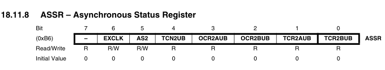
When making any changes to the timer registers when the timer is been clocked asynchronously, you need to be careful as the data you write is clocked in after 2 clock cycles of the timer. For this reason, there is the ASSR register which allows you to check if the data you have written to the timer registers have been successfully updated. If you don’t wait and say go to sleep then the value you wrote might not have been updated.
Lastly we need to wait 1 second for the 32.768KHz oscillator to stabilise.
.
Variables
// Overflow for 32.768KHz crystal
ISR(TIMER2_OVF_vect) {
  unix_timestamp += 8; // Increment by 8 seconds
  //unix_timestamp += 1; // Increment by 1 second
}
The overflow of the timer will increment a timestamp counter.
volatile uint32_t unix_timestamp = 1000; // Current unix timestamp (change this to the current time)
byte trigger_location = 0; // Where in the trigges array we are up to
uint16_t trigger_delay = 0; // Keep track of the time passed since the LEDs were lit
int leds_location = 0; // Where in the leds animation array we are
Let’s look into our variables. First we have the unix timestamp which if you haven’t heard of before, is a counter of the number of seconds since Jan 1, 1970. You can visit www.epochconverter.com to get the current time as the unix timestamp or convert a date/time to the unix timestamp. When you program your ATmega you’ll have to change this to the current time.
Next is the trigger location which tells us where in the triggers we are up to (more on this soon). Because we don’t want to keep the LED animation constantly repeating itself and thus draining our battery, we add a delay of x seconds before the animation is repeated once. This trigger delay variable is incremented by 8 every timer overflow – so the minimum delay is 8 seconds (you can change this if you like). Lastly we have the leds location which keeps track of where in the LEDs animation we are.
// Triggers array listed in ascending order
uint32_t triggers[3][6] = {
  {1000, 1020, 8, 0, 127, 10},
  {1030, 1050, 8, 128, 319, 10},
  {1060, 999999, 8, 321, 455, 30}
};

// LEDs animations array
prog_uchar ledProgram[] PROGMEM = {
  // First animation - single firework
  16,2,128,0,2,64,0,8,
  8,128,2,0,0,130,0,16,
  16,2,128,0,2,64,0,8,
  ...
}
Here are the two arrays we’ve referenced. The triggers array contain the start timestamp for the animation (element 0), the end timestamp, seconds to wait before re-displaying the animation (delay), end location in ledProgram array (because we deincrement our leds_location), start location in ledProgram array and speed of the animation (higher means is slower animation).
// Redraw the 8x8 matrix by reading the data out of the sections array
void redrawMatrix(void) {
  leds_location = leds_location - 7; // Go to the start of the current column

  for (byte row = 0; row < 8; row++) {
    byte data = (unsigned char) pgm_read_byte(&ledProgram[leds_location]);
    leds_location++;
    ...
  }

  leds_location = leds_location - 9; // Go to the end of the next column
  if (leds_location < 0) { leds_location = 0; } // Prevent underflow
}
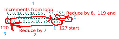
Here’s the new redraw matrix function using PGM. Modifying the leds location variable is a little confusing but basically we go to the start of the current row, increment the variable and then reduce it by 9 to go to the end of the next row and begin again; underflow is possible here so we avoid that.
.
Main code
Now we move onto the main code.
// Check we have reached the start time
if (unix_timestamp >= triggers[trigger_location][start_time]) {
  leds_location = triggers[trigger_location][start_location]; // Set the leds start location

  // Increment trigger_delay until it's time to light up the LEDs
  trigger_delay += 8; // Increment by 8 seconds
  //trigger_delay += 1; // Increment by 1 second

  // Light up the LEDs when delay time is over
  if (trigger_delay >= triggers[trigger_location][delay_time]) {
    // Turn off timer overflow as the timer is still running
    TIMSK2 &= ~(1<<TOIE2);

    // Draw LEDs
    while (leds_location > triggers[trigger_location][end_location]) {
      redrawMatrix(); // Redraw the new 8x8 matrix with the next animation

      // Light up the LEDs a few times to fill in time
      for (int i = 0; i < triggers[trigger_location][animation_speed]; i++) {
        lightLED();
      }
    }

    trigger_delay = 0; // Reset trigger delay
    TCNT2 = 0; // Reset timer to 0 count as it's still counting
    while ((ASSR & ((1<<TCN2UB))) != 0); // Wait until one TOSC1 cycle has elapsed
    TIFR2 = 0; // Clear the Timer/Counter2 Interrupt Flags
    TIMSK2 |= (1<<TOIE2); // Enable overflow interrupt
  }

  // Check if we reached the end time, increment trigger_location to the next start time
  if (unix_timestamp >= triggers[trigger_location][end_time]) {
    // Check if there is a next trigger
    if (trigger_location < sizeof(triggers) / sizeof(uint32_t)) {
      trigger_location++;
      trigger_delay = 0;
    }
    else {
      // Sleep forever since there are no more triggers
      system_sleep();
    }
  }
}

// Wait until one TOSC1 cycle has elapsed
TCCR2A = 0;
while ((ASSR & ((1<<TCR2AUB))) != 0);
system_sleep_pwr_save(); // Sleep for 8 seconds until the timer wakes us up
There is quite a bit to the main code, first we check if the current time is more than the start trigger time, if so set the leds location back to the start of our animation. We increment our trigger delay because we would have woken up from the timer overflow of 8 seconds (I’ve left the 1 second commented out if you wanted to change all the code to work on 1 second timer overflows).
If the delay time variable is more than the delay time from the triggers array, we turn off the timer overflow because the animation could go for more than 8 seconds, we show the animation and reset the trigger delay and the timer value and re-enable the timer overflow. We check if the current time is more than the end time, if it is we check if there are any more triggers and if not we sleep forever.
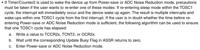
Lastly we need to wait until one TOSC1 (timer) cycle has occurred and then we go to sleep, otherwise we would wake up multiple times on the same overflow interrupt if no led animations were to occur.
I wanted to make sure that the TOSC1 cycle was actually happening so checked it with the logic analyser and I could confirm it was occurring. The next question is how accurate is our 32.768 timer?
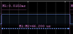
I changed the timer to overflow every 1 second and it gives us 999.808ms. Assuming that the logic analyser is completely accurate this means our 32.768 KHz timer is .000192% -/+ accurate. Once we put everything on a PCB and put on the load capacitors this value will change. Over 24 hours we would lose or gain 16.5 seconds (86400 x .000192). For over half a year it would be 48 minutes which isn’t too bad at all seeing as this project isn’t relying on perfect watch like accuracy.
.
Flickering on the bottom row
I found that when running my animations there was a slight flicker on the bottom row and playing around the delay / redraw time didn’t help.
// Light the LEDs by going through each row/column and wait a little while
void lightLED(void) {
for (int x = 0; x < 9; x++) {
  if (x < 8) { // Normal lighting of the LEDs
    // All columns stay low (off) and rows that have a 1 go low (on)
    ...
    // Set the column to go high (on)
    ...
  }
  else { // Our dead period to make the last row not flicker
    // Turn off all LEDs
    PORTB &= ~((1<<PB5) | (1<<PB4) | (1<<PB3) | (1<<PB2) | (1<<PB0));
    PORTC &= ~((1<<PC3) | (1<<PC2) | (1<<PC1) | (1<<PC0));
    PORTD &= ~((1<<PD7) | (1<<PD6) | (1<<PD5) | (1<<PD4) |  (1<<PD3) | (1<<PD2) | (1<<PD1));
  }

  _delay_ms(2); // Delay a bit so the LEDs light up for enough time
}
Eventually I found we need to include a “dead time” after we have lit the bottom row and then move up to the top row, because we already have this “dead time” as the delay in-between lighting each row.
.
Conclusion
https://www.youtube.com/watch?v=GXFvrg3kfjo
Download AT_Mini_LED_Matrix_v0.2
Overall I’m happy with how it all works, I shouldn’t have to make any more changes to the code as it seems to work well. Now all that’s left is to order the PCBs and put one together!


