I’ve had the HobbyKing Rattler for some time now and I’ve been making small modifications here and there which have accumulated over time and has gotten to the point where it would be nice to have everything on a custom PCB.
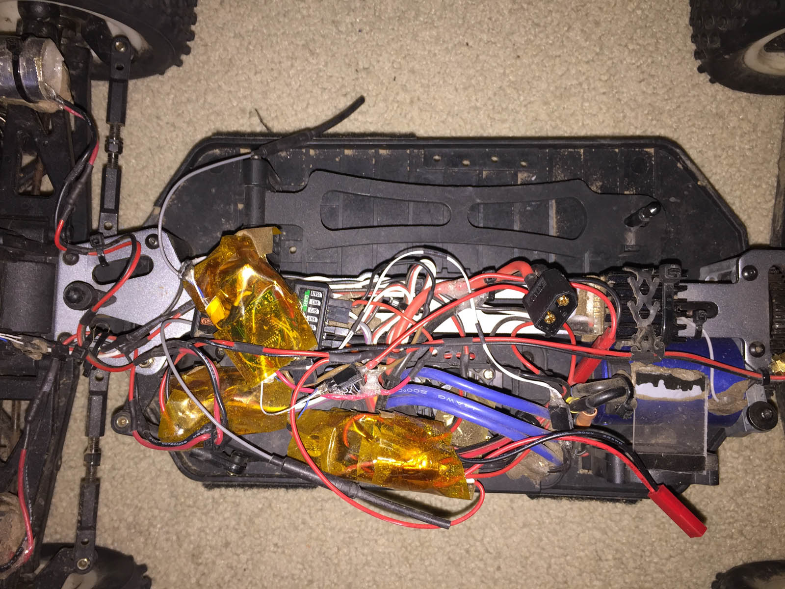
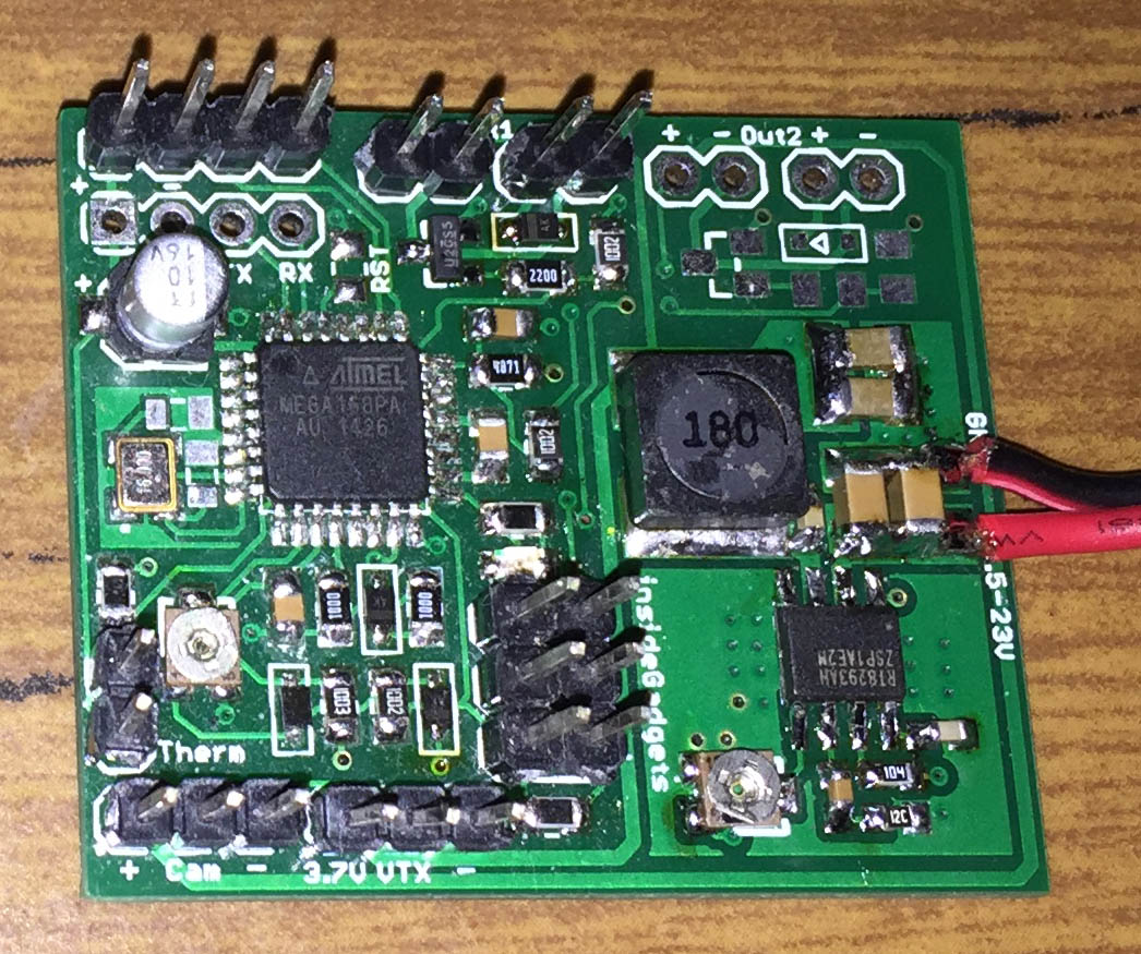
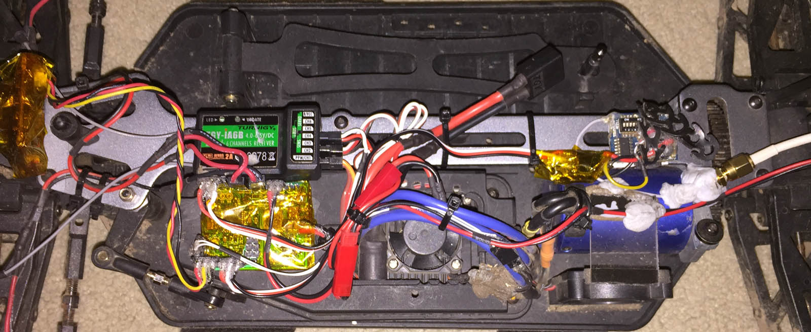
Here’s how everything looks at the moment, pretty messy with kapton tape wrapped around each separate board, we have a large DC-DC converter bought off Ebay a while back for the video transmitter (VTX), an ATtiny control board for the lights/connecting to the receiver and an ATmega with another board doing the temperature/video osd. On the right, we have the finialised PCB.
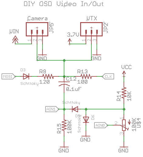
Let’s start off with the video OSD as it’s what the whole board revolves around, I’m using DIY OSD which uses an ATmega with some resistors, diodes and capacitors to overlay text over the screen and it works fairly well. It’s written in Arduino so I’m going to have to use that and I took out the GPS code references so we can fit it into an ATmega168. There are other solutions like Minimosd use a dedicated chip (MAX7456) to do the overlay and the text it generates is better however I wanted to keep things simple and small.
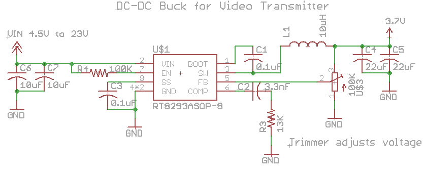
Next we’ll replace our Ebay DC-DC module and put that on our board for the VTX. I’ve played around with the Richtek RT8293A DC-DC before, so was able to pop that into my PCB, make it compact at 22mm x 17mm as I’d only be drawing 500mA to 1A max from it and the 100K trimmer allows us to adjust output voltage. I’ve cut this module out from my extra PCBs and used this on other devices too and so far in the 2-3 months I’ve tested it, it worked well, I had one device short the output (until I realised it was the Vtx for another project) and the RT8293A survived.
// Setup pin change interrupt on receiver pin 1 (PC3)
sbi(PCICR, PCIE1);
sbi(PCMSK1, PCINT11);

// Setup Timer1 for Fast PWM
...
// Setup Timer0 to count the microseconds after pin 2 goes high
...

// Time how long the receiver channel is high for
ISR(PCINT1_vect) {
  if (PINC & (1<<receiverLightsIn)) {
    TCNT0 = 0; // Reset counter
  }
  else {
    lightsPWMOutput = (TCNT0 - 50) * 3; // Remove 1ms high period and then multiply the variable high period to occupy close to the full 8 bit variable

    // Check if output should be on or off
    if (lightsPWMOutput <= 60) {
      lightsPWMOutput = 0;
      cbi(TCCR1A, COM1A1);
    }
    else if (lightsPWMOutput >= 200) {
      lightsPWMOutput = 255;
      sbi(TCCR1A, COM1A1);
    }
    else {
      sbi(TCCR1A, COM1A1);
    }
  }
}
For the front and back lights I originally had an ATtiny connected to the receiver so we’ll have to integrate this into the ATmega, I’ve processed the RX signals with the Arduino before so I can use some of that code. To make things as quick as possible because we don’t know when the RX signal will go high, we setup a pin interrupt on our receiver pin, if it’s high we reset the counter and when it goes low we do our processing to see how long it was high for.
We have a fast PWM timer for the lights output and depending on the dial on the transmitter, we adjust the duty cycle. We reduce our timer result by 50 to remove the 1ms usual high period and we give it a little bit of grace by checking if the timer value was less than 60 and if so turning off the PWM output, otherwise we turn on the output. On the PCB, all we have is a SOT23 N mosfet (IRLML6344TRP) with related circuitry, one output is driven by the DC-DC and one by the battery.
I went with 2x 1W LEDs for the front lights, wrapped them up in metal tube, glued it all so they represent the car’s headlights, works alright, the focus could be a tad better. For the back lights I went with an LED strip (used to have 6x red LEDs before) and since we have our 2nd output driven by the battery we can connect them up there.
double thermistorTemp(int RawADC) {
  double Temp;
  Temp = log((double) ((10240000/RawADC) - 10000) / 10000); // We divide by our thermistor's resistance at 25C, in this case 10K
  Temp = 1 / (0.003354016 + (0.0002569850 * Temp) + (0.000002620131 * Temp * Temp) + (0.00000006383091 * Temp * Temp * Temp));
  Temp = Temp - 273.15; // Convert Kelvin to Celsius
  return Temp;
}
I re-purposed the RSSI which displayed on the bottom left to be the temperature readout, we can just use the thermistorTemp Arduino function and it’s sorted. I placed the thermistor on the ESC’s heatsink.
And that’s all there is to all of these mods, here’s how the car looks now, much neater than before. Download iG_Rattler_Car_Mods
Also as a side note I discovered the Xref labeling scheme in Eagle from a schematic I saw when looking for open source ESC and it’s made my schematics so much easier to read and layout, no more wires going everywhere, highly recommend using it!


