From our last part we looked at choosing capacitors for our LDO, testing our I2C timing, switching to a 1Mbit EEPROM and using EEPROM page writes. This time we’ll look at adding in the TMP102 sensor, experimenting with I2C pull-ups, re-testing the voltage switcher diode and other little improvements.
It has been a good while since I’ve worked on this project, though it’s not all bad, it does give me a chance to re-look at the project and pick up on things I might have missed.
Adding the TMP102
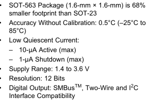
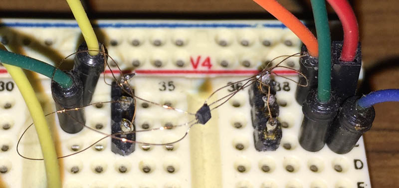
The TMP102 is a very small I2C temperature sensor with 0.5C accuracy (typical, -25C to 85C), 12 bit resolution, 1.4 to 3.6V supply and low current at 1uA shutdown and 10uA active plus it’s much smaller than what I thought so I had to use enamel wire to connect to it.
#define TMP102_TEMP_REG 0x00
#define TMP102_CONFIG_REG 0x01
#define TMP102_CONFIG_SD_MODE 0x01
#define TMP102_CONFIG_EM 0x10
#define TMP102_CONFIG_ONESHOT 0x80
...
if (!soft_i2c_master_start((deviceAddr<<1) | I2C_WRITE)) return false;
if (!soft_i2c_master_write(TMP102_CONFIG_REG)) return false;
if (!soft_i2c_master_write(TMP102_CONFIG_SD_MODE)) return false;
if (!soft_i2c_master_write(TMP102_CONFIG_EM)) return false;
soft_i2c_master_stop();
By default the TMP102 operates in a continuous conversion mode where it samples the temperature and puts it in a register at power on, we should disable this feature by enabling shutdown mode (SD).
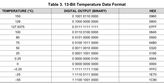
We change from 12bit data mode which lets us measure -55 to 128C to 13bit mode which does -55 to 150C by setting the extended mode bit and write the above changes by referencing the configuration register (0x01) first.
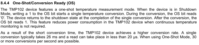
Since the TMP102 is now shutdown, when we want to do a conversion we use one shot (OS) mode which typically takes 26 ms.
// Turn on one shot (plus re-set to 13bit and shutdown mode (SD))
if (!soft_i2c_master_start((deviceAddr<<1) | I2C_WRITE)) return false;
if (!soft_i2c_master_write(TMP102_CONFIG_REG)) return false;
if (!soft_i2c_master_write(TMP102_CONFIG_SD_MODE | TMP102_CONFIG_ONESHOT)) return false;
if (!soft_i2c_master_write(TMP102_CONFIG_EM)) return false;
soft_i2c_master_stop();

// Wait 32ms for the temperature conversion to complete
watchdog_sleep(T32MS);

// Read temperature and combine bytes
if (!soft_i2c_master_start((deviceAddr<<1) | I2C_WRITE)) return false;
if (!soft_i2c_master_write(TMP102_TEMP_REG)) return false;
if (!soft_i2c_master_restart((deviceAddr<<1) | I2C_READ)) return false;

uint8_t low, high;
high = soft_i2c_master_read(0);
low = soft_i2c_master_read(1);
soft_i2c_master_stop();

int combinedResult = ((high << 8) | low) >> 3;
When setting the one shot bit we also re-set the other bits we originally set at startup too, wait 32ms with the watchdog timer for the conversion to finish, then read the 2 registers for the result and combine them together.
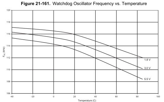
The watchdog timer as you may know is affected by voltage/temperature. Temperature would be the bigger problem however according to the characteristics graph, we should only see a 6% change so our 32ms wait can at worst be 30ms to 34ms, which will do the trick.
Testing other I2C methods
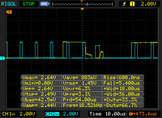
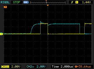
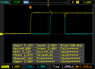
At the moment, the ATtiny is driving the I2C lines directly and switching to internal pull ups, it works well though when I check it on the scope there is some strange drop off that happens for the SDA line (yellow) and you can also see that the SCL line’s (blue) voltage drops a bit too at the acknowledge bit. In the picture to the right, I measured the voltage of the coin cell and you can see quite a bit of drop so something is not quite right.
After a bit of experimentation, I found that adding a adding 2x 330 ohm resistors in series with the SDA line resulted in a better reading and the SDA voltage went back to normal so it looks like there must have been quite a bit of current draw before. Measuring the average current with a multimeter showed it too, 130uA average before and 120uA after.
Nothing appears to be wrong with the code from what I briefly tested but since I’m using a resistor already I might as well try modify the code and using external I2C pull ups instead, the proper way that I2C should be done.
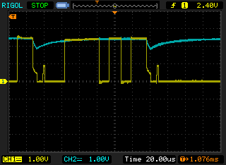
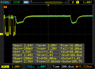
I tested different pull ups, 10K (shown to the left) and 1.5K (on the right) seems pretty reasonable and the average current draw seems to be about the same as before. The code is pretty much the same as before except now all we do is change the pins between tristate (DDR 0 & PORT 0) and sink (DDR 1 & PORT 0). All in all, this did take a few days to play around with it all but I will be doing the I2C right and using external pull ups.
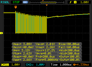
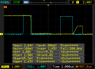
Whilst testing the I2C, I noticed that the voltage was dropping off quite a bit (down to 1.8V some times) when the EEPROM was doing it’s write, adding a 10uF electrolytic capacitor right next to the EEPROM solved that issue, I’ll need to do further testing when I swap it out with ceramic capacitor. Even with the capacitor it does drop over the span when it does the 32 byte data transfer which lasts 4.3ms and then add 5ms for the actual write.
Testing the voltage switcher diode
From memory I thought everything was good however I decided to re-test the current draw when powered from a 3V coin cell battery and found that there was a good 5-10uA leakage current from it. I swapped out the diode for another, the leakage was better however when plugging in the USB, it drops the 3.3V from the LDO to about 2.6V which is no good.
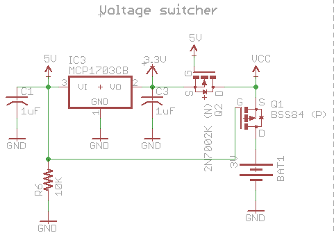
So I’ve gone with an N mosfet instead of the diode, gate is attached to the USB 5V so when it’s connected, it will turn on otherwise it will be kept off, seems to work well.
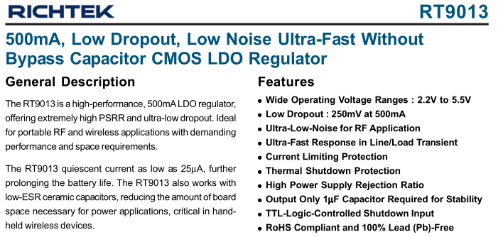
When doing a restock of some parts, it appears that the Richtek RT9166 LDO I went with (and most Richtek parts) are being taken off my suppliers site, so it’s last stock remaining only. The RT9166 price has doubled/tripled since I last bought it so I choose to go with the Richtek RT9013 LDO which is a SOT23-5, cheap and a similar footprint size plus there are alternatives from Microchip for about the same price like the MIC5501 and TC1016.
Small Improvements/Fixes
Since I’ve added the TMP102 and I would like to make this a higher end temperature logger than the SATVL, to keep things simple in configuration I will remove the 10K thermistor option so this project will only come in 1 variant – the TMP102.
// Delay 6ms for the write to complete. This value depends on the EEPROM you use so check your EEPROM's datasheet.
_delay_ms(48); // 48ms / 8 clock divider gives 6ms delay
Before I was delaying a few ms for the EEPROM to finish it’s write but really we don’t need to do that at all, once we finish writing our data to the EEPROM, we just go back to sleep and let the EEPROM do the write. (And the clock divider I say should really be a clock multiply by 8 as we run at 1.5MHz instead of 12Mhz)
// Page write blank bytes (0xFF) to 1 page (256 bytes) on the EEPROM
void soft_i2c_eeprom_page_blank(uint8_t deviceAddr, uint16_t pageAddress) {
	...
	// Write all 0xFF
	for (uint8_t x = 0; x < 255; x++) {
		soft_i2c_master_write(0xFF);
	}
When I was blanking the EEPROM page, the last byte always came out as 65428 or similar, found it was because I wasn’t writing to all 256 bytes, so I bumped it up to a uint16 and the end to 256.
USB_PUBLIC uchar usbFunctionSetup(uchar data[8]) {
	...
	if (rq->bRequest == USB_TRANSFER) { // custom command is in the bRequest field
		if (dataCount <= endCount) {
			soft_i2c_eeprom_read_bytes(EEPROM_ADDR, dataCount);
			dataCount += 252;
		}
		...

// Read 252 bytes from the EEPROM device and put in the reply buffer
uint8_t soft_i2c_eeprom_read_bytes(uint8_t deviceAddr, uint32_t readAddress) {
	...
	// Read the bytes
	for (uint8_t x = 0; x < 252; x++) {
		replyBuf[x] = soft_i2c_master_read(0);
	}
	soft_i2c_master_read(1);
Before I was reading 2 bytes at time and sending that back to the PC, I’ve now changed it to read 252 bytes at once and send those over to the PC at once, that should give a little bit of improvement.
ISR(PCINT0_vect)
	_delay_ms(20); // Multiply by 8 for real delay ms

	// Check if button is being held down for 2 seconds, if it is, switch the state of logging variable
	uint8_t pinHeldCounter = 0;
	while (PINA & (1<<buttonPin)) {
		_delay_ms(20); // Multiply by 8 for real delay ms
		pinHeldCounter++;
		...
	}

	// Wait for button release (so we don't generate another interrupt when released)
	while (PINA & (1<<buttonPin)) {
		_delay_ms(20); // Multiply by 8 for real delay ms
	}
}
Since adding the button to turn the logging on and off, I’ve got no need to use the WDT to reset the AVR when the USB is plugged in (probably for the best). When the USB is plugged in, it will only activate if the logger isn’t logging. I’m also thinking of adding a mission critical logging mode, so only removing the battery will stop it logging. Due to having the button, if it’s pressed say when we are on our 16th byte of our 32 byte eepromBuffer, we need to write that buffer to the EEPROM before we stop logging, so I’ve implemented that too.
Download MiniTempLogger_R2
For the next part, I’ll look at adding the RTC and do more testing, estimate battery life and durability tests leaving it running a few days too.
Building the Mini Temp Logger Part 1: Re-design of the SATVL/A25TTL into another product
Building the Mini Temp Logger Part 2: LDO capacitors checks, testing I2C timings and using EEPROM page writes
Building the Mini Temp Logger Part 3: Using the TMP102 sensor, testing I2C methods and other small improvements
Building the Mini Temp Logger Part 4: Adding RTC and Estimating battery life
Building the Mini Temp Logger Part 5: PCBs arrived and RTC Testing
Building the Mini Temp Logger Part 6: RTC Auto Trim & Voltage reading
Mini Temp Logger v1.0 Released


