From our last part we looked at adding in the TMP102 sensor, experimenting with I2C pull-ups, re-testing the voltage switcher diode and other improvements/fixes. This time we’ll look at adding in the RTC including programming the time from the PC, more bug fixes, estimating battery life and briefly looking at some logging results.
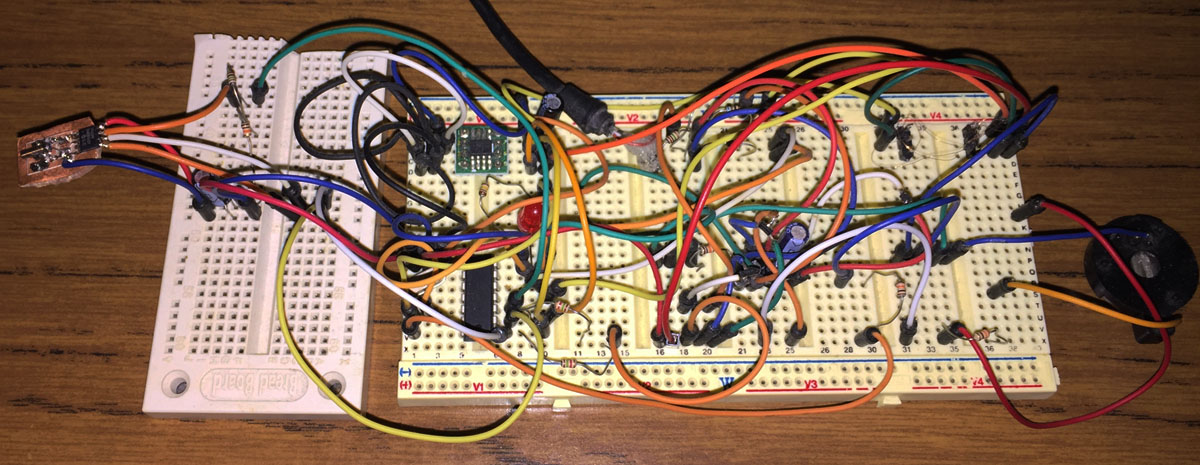
I started off re-designing the RTC crystal layout which I would also make into a little board to connect up to the breadboard and since I already have a RTC clock project I can use that for reference.
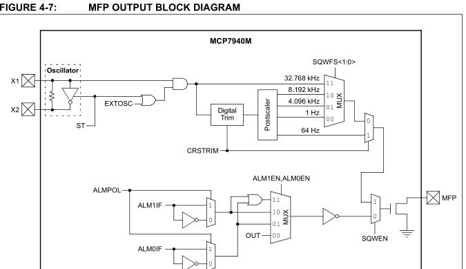
The MCP7940M has the option to output a 1 Hz square wave which is what we’ll use to wake up the ATtiny every second. We no longer need to use the watchdog timer which takes about 4uA when in use where as the RTC takes 1.2uA.
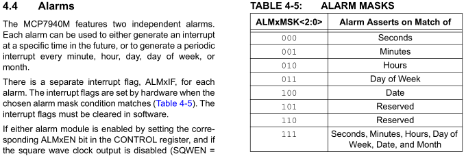
An alternative is to use the alarm capability build into the RTC to wake us up however this would mean that for 1 second logging, you would need to constantly reconfigure the alarm for the next second which could be complicated in the end and you might spend even more current reconfiguring it however for longer logging delays say every minute or hour it would make sense but I’ve opted to keep everything simple for the moment and just use the 1Hz output.
Speaking of the 1Hz, it’s an open-drain output with 50% duty cycle so we need to connect it up to Vcc and the recommended value is 10K but that would consume too much current so I went with a 1M resistor instead which seems to work fine for the moment (I’ll need to test in different environments), may have to go up to 100K if need be.
// Copy RTC time to EEPROM so we know the start date/time
save_rtc_time_to_eeprom();

// Set clock output at 1Hz
soft_i2c_master_start_with_8bit_address(RTC_ADDRESS, RTC_CONTROL, NOREPEATSTART);
soft_i2c_master_write(RTC_CONTROL_SQWEN_BIT);
soft_i2c_master_stop();

// Start the RTC (if it's not already started, this means the RTC stopped or RTC time hasn't been programmed)
soft_i2c_master_start_with_8bit_address(RTC_ADDRESS, RTC_RTCSEC, REPEATSTART);
uint8_t isRtcRunning = soft_i2c_master_read(1);
soft_i2c_master_stop();
if (!(isRtcRunning & RTC_RTCSEC_ST_BIT)) {
	soft_i2c_master_start_with_8bit_address(RTC_ADDRESS, RTC_RTCSEC, NOREPEATSTART);
	soft_i2c_master_write(RTC_RTCSEC_ST_BIT);
	soft_i2c_master_stop();
}
When logging starts we firstly save the RTC current time to the EEPROM so we can recall when the logging started, set the clock output to 1Hz and start the RTC if need be. If it wasn’t started already that means that the time hasn’t been programmed or the battery was disconnected/reconnected but we still want to log anyway.
// Wait for RTC 1Hz pulse high and low (500ms length each)
void rtc_sleep_1_sec(void) {
	system_sleep();
	_delay_us(10); // x8 clock = 80us

	system_sleep();
	_delay_us(10); // x8 clock = 80us
}
The ATtiny has a pin interrupt configured on that 1Hz output pin, we will have 2 interrupts per second so we’ll need to account for that by sleeping twice and putting in a bit of a delay so we don’t accidentally re trigger, I found 42us for the rise time and 12ns for the fall time so I’ll just double the larger of the two.
uint16_t delayCount = delaySeconds + (delayMinutes * 60) + (delayHours * 3600);
while (delayCount != 0 && logging == true) {
	rtc_sleep_1_sec();
	delayCount--;
}

if (delayDays >= 1) {
	uint32_t delayCount = delayDays * 86400;
	while (delayCount != 0 && logging == true) {
		rtc_sleep_1_sec();
		delayCount--;
	}
}
The delay counter code has also been changed to accommodate the RTC too, it’s simpler and I moved the days delay to it’s own loop as it needs 32 bit variables to calculate the delay times in seconds and to hopefully keep the power a bit lower if you aren’t delaying using days (16bit vs 32bit variables).
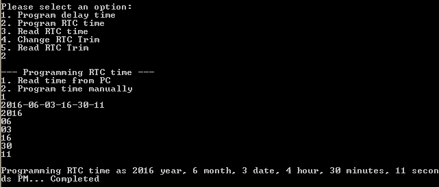
As part of the RTC, we’ll need to be able to enter in the time, I’ve made it so it can be either manually or pick it up automatically from the PC. The RTC has the ability the trim the oscillator up to 129ppm +/-, I’ve covered this briefly before but it’s also worth including the ability to read and set this value too (the MCP7940M data sheet in one spot has the output rates back to front).
buffer[0] = PROGRAM_RTC_TIME;
buffer[8] = 0;

time_t rawtime;
struct tm* timeinfo;
char timebuffer[80];
time (&rawtime);
timeinfo = localtime (&rawtime);
strftime (timebuffer,80,"%Y-%m-%d-%H-%M-%S",timeinfo);
printf("%s\n", timebuffer);

int tokenCount = 7;
char *token;
token = strtok(timebuffer, "-");
while(token != NULL) {
	...
}
...
printf("\nProgramming RTC time as 20%i year, %i month, %i date, %i hour, %i minutes, %i seconds ", rtcTimeYear, rtcTimeMonth, rtcTimeDate, rtcTimeHour, rtcTimeMinutes, rtcTimeSeconds);
...
usb_control_msg(handle,
	USB_TYPE_VENDOR | USB_RECIP_DEVICE | USB_ENDPOINT_OUT,
	USB_DATAFROMPC, 0, 0, buffer, 9, 5000); // Write 9 bytes (including null ending character)
Sleep(500);

// Verify the RTC time is correct
int nBytes = usb_control_msg(handle,
		USB_TYPE_VENDOR | USB_RECIP_DEVICE | USB_ENDPOINT_IN,
		USB_RTCTIMESEND, 0, 0, (char *)buffer, sizeof(buffer), 5000);
...
if (readRtcAmPm == rtcTimeAmPm &&
	...
	 printf("Completed\n");
}
I slightly changing how data is sent from the PC to the device because we are adding more functionality, we need to check to see what the PC is actually requesting – change delay time, RTC time read/send or Trim read/send. This is done via the first byte of the buffer, in the case above, we are changing the RTC time, we read the clock from the PC, tokenise the values into the right spots and send it and I also added a verify stage to read back everything matches.
// Change RTC time to MCP7940M format
if (rtcSec > 10) {
	rtcSec = ((rtcSec / 10) << 4) | (rtcSec % 10);
}
rtcSec |= RTC_RTCSEC_ST_BIT; // Set RTC start bit
if (rtcMin > 10) {
	rtcMin = ((rtcMin / 10) << 4) | (rtcMin % 10);
}
...
As part of the loading/retrieving the RTC time, we need to convert the time to suit the MCP7940M format and vice versa.
Small Improvements/Fixes
When testing inserting and removing the USB, a few times the LED would stay lit up like it hadn’t gone back to sleep and that also meant it didn’t have enough time to switch to the slower clock rate. I found that for some reason I was sensing the USB- line instead of the 3V LDO and changed over PCINT1 to PCINT2 and it all seems good now.
// Once our 32 byte buffer is full, write it to the I2C EEPROM
if (eepromBufferCounter >= EEPROM_BUFFER_LENGTH) {
	soft_i2c_eeprom_page_write(EEPROM_ADDR, eepromPageCounter, eepromPageByteCounter, eepromBuffer, EEPROM_BUFFER_LENGTH);
	eepromPageByteCounter += eepromBufferCounter;
	eepromBufferCounter = 0;

	// If we have almost filled up the current page (224 out of 256 bytes) and we aren't on the last page of the EEPROM (511)
	// then blank the next page
	if (eepromPageByteCounter == 224 && eepromPageCounter < 511) {
		watchdog_sleep(T16MS); // Wait for page write before to finish
		soft_i2c_eeprom_page_blank(EEPROM_ADDR, eepromPageCounter+1);
	}
With the next page blanking, instead of leaving it for the last minute when the current page is full, we might do it before it’s full, in case there was ever a chance that the page was full, the user ends the logging and we didn’t have a chance to blank the next page as that blank page would tell us when to stop the data transfer back to the PC. Also the page blanking didn’t seem to be working quite as planned, it wouldn’t blank the next page for some reason, I discovered that I wrote the 32 byte to the page but then didn’t wait for the EEPROM to complete the write before blanking the next page so a 16ms watchdog sleep sorts that out.
Estimating battery life
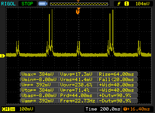
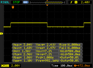
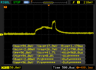
I placed a 330 ohm resistor between the battery and checked the current pulses on the scope, I had it set to do 1 second logging and we can see the 2 times every 1/2 second, the ATtiny wakes up due to the RTC output.
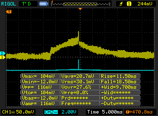
One thing I noticed is that the ATtiny drew some current for a good 8ms or so before it set a pin high (blue).
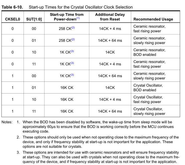
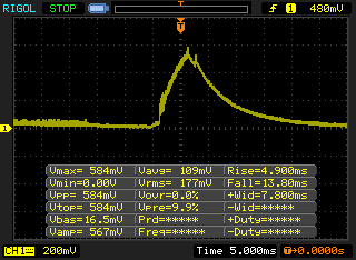
It turns out it’s due to the crystal start up time I’ve selected (last one in the table), it takes 16K clocks to start up from power down so it would be ideal to make this as short as possible. I went with the CKSEL0 = 1 and SUT = 00 option as it’s 1K clocks and the note down the bottom say it can be used with crystals “when not operating close to the maximum frequency of the device” or “if frequency stability at start-up is not important” which when logging, we are down to 1.5MHz (12MHz / 8) so it suits plus we don’t need the crystal to be too accurate at startup either. Also since we aren’t near the 20MHz max frequency of the ATtiny, we shouldn’t run into any issues when plugging in the USB.
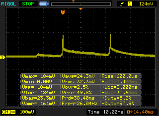
Upon re-testing the start up, it’s about 1ms, so that’s a decent power saving if we’re waking up every second. We have a few sources that generate our power consumption and for every 100mV on the vertical scale it’s 0.3mA. Once every half a second when the RTC wakes us up (as above), it’s about 1.5ms but we’ll say 2ms and 0.2mA average.
With 1 second logging, we write to the EEPROM every 16 seconds, we load data into the EEPROM and 5ms for the write which according to the EEPROM datasheet will probably be 4mA so we’ll say 15ms but it looks like we only peaked at 1.8mA, this is likely due to the 10uF capacitor I have on the EEPROM, so lets go with 3mA average. Also every 128 seconds, we’ll do a page blank so it will be about the same current draw/time.
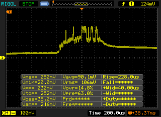
Every 1 second, we turn on the TMP102 to start the conversion (about 1ms at 0.6mA) , watchdog sleep for 32ms (another 2ms at 0.2mA) and then wake up again to retrieve the temperature data (about 1ms at 0.6mA again) so lets say 6ms at 0.8mA.
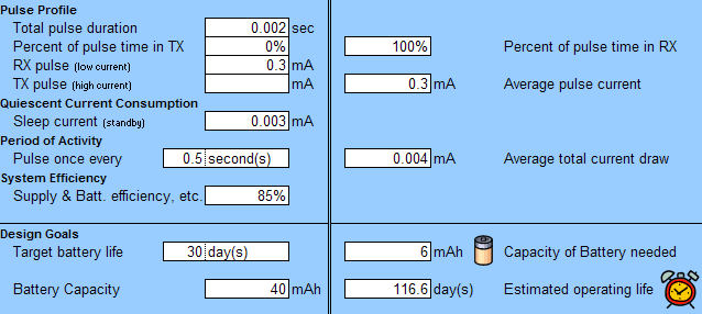
After combining everything together, it looks like with a 40mAh battery with 1 second logging it should last 116 days which would give 18 hours of results per logging session and 154 times you could log for that amount, which isn’t too bad. For 2 second logging gives 173 days, 3 second logging gives 207 days and 4 second logging gives 229 days.
Download battery-life-calculator with 3 pulses and MiniTempLogger_R3
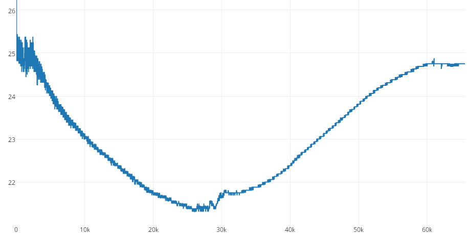
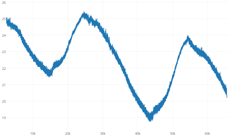
I left the RTC logging running at 1 second and 3 seconds intervals around the house and used Plot.ly to do the graphs (plus you can zoom into them on their site) – 1-3-Sec-Logging
Now all that’s left is to double check the breadboard matches the schematic, write the code to output and increment the date/time when retrieving the data, test the replacement 3.3V SOT23-5 LDO, make a few changes to the board layout and place the order for some boards.
Building the Mini Temp Logger Part 1: Re-design of the SATVL/A25TTL into another product
Building the Mini Temp Logger Part 2: LDO capacitors checks, testing I2C timings and using EEPROM page writes
Building the Mini Temp Logger Part 3: Using the TMP102 sensor, testing I2C methods and other small improvements
Building the Mini Temp Logger Part 4: Adding RTC and Estimating battery life
Building the Mini Temp Logger Part 5: PCBs arrived and RTC Testing
Building the Mini Temp Logger Part 6: RTC Auto Trim & Voltage reading
Mini Temp Logger v1.0 Released


