From our last part we received our PCBs, did some RTC crystal testing, some of the results that I couldn’t explain was that it drifted a few seconds some days whilst my home clock that used the same RTC didn’t. After a lot more testing (weeks, ouch!), it turns out that my computer was the cause, its clock changes by a few seconds every few hours, even though I had it syncing up in the mornings, so I switched to using an online time website. After a bit of calibration, I left it running for 10 days and it’s only 1 second slower so I’m happy with that result.
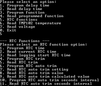
I was previously thinking about adding in a RTC auto trim function to trim based on temperature which I thought might help to resolve the initial issue I had but it wouldn’t have actually done much (due to my timing issue), in the end I implemented it and it will work when it’s logging or not plus now the RTC related functions in the interface program have a dedicated section. As per the crystal PDF specs, they had a formula for this purpose: -0.035 x ((T – To) x (T – To)). We can program in the interval (seconds, minutes, hours or days) for the auto trim function to run, whether we want it on or off and a few options to read back the PPM trim value calculated and how it would affect the current static RTC trim.
// Read RTC auto trim interval time
uint8_t autoTrimIntervalSeconds = eeprom_read_byte((uint8_t*) autoTrimIntervalLocation);
...

// While we aren't logging and the USB isn't plugged in
while (logging == false && (!(PINA & (1<<usbSensePin)))) {
	int tempResult = tmp102_read_temp(TEMP_ADDR);
	set_trim_from_temp(tempResult);

	// Wait the trim interval
	uint32_t autoTrimInterval = autoTrimIntervalSeconds + (autoTrimIntervalMinutes * 60) + (autoTrimIntervalHours * 3600) + (autoTrimIntervalDays * 86400);
	while (autoTrimInterval != 0 && logging == false && (!(PINA & (1<<usbSensePin)))) {
		rtc_sleep_1_sec();
		autoTrimInterval--;
	}
}
The auto trim computes the auto trim interval into a single variable, has a counter to wait for the specified interval unless we press the button to start logging or plug it into the PC.
void set_trim_from_temp(int tempResult) {
	if (tempResult >= 0x1C90 && tempResult <= 0x1FFF) { // Convert negative temps
		tempResult &= 0x1FF;
		tempResult--;
		tempResult ^= 0x1FF;
	}
	tempResult = tempResult * 0.0625;

	// Calculate how much trim ppm we need
	rtcAutoTrimVal = ((tempResult - 25) * (tempResult - 25)) * 0.04;

	// No trim? Set to 128 so it's easier to calculate from (128 also means no trim enabled)
	if (rtcTrim == 0) {
		rtcTrim = 128;
	}

	// Add trim calculated to existing static RTC trim
	rtcAutoTrimCalc = rtcTrim - rtcAutoTrimVal;
	if (rtcTrim > 128 && rtcAutoTrimCalc < 128) {
		rtcAutoTrimCalc = 128 - rtcAutoTrimCalc;
	}
	else if (rtcTrim < 128) {
		rtcAutoTrimCalc = rtcTrim + rtcAutoTrimVal;
		if (rtcAutoTrimCalc >= 127) { // Limit max
			rtcAutoTrimCalc = 127;
		}
	}

	soft_i2c_master_start_with_8bit_address(RTC_ADDRESS, RTC_TRIM, NOREPEATSTART);
	soft_i2c_master_write(rtcAutoTrimCalc);
	soft_i2c_master_stop();
}
Inside the auto trim function, we read the temperature and use the formula to calculate the trim, I used 0.04 in the formula to keep things simple. As an example, if the current temperature is 31C, the result would be 1.44PPM which would round down to 1. Now that we have the PPM to change by, we need to apply it to the static RTC trim but since the RTC trim setting uses the FSB to signify if it’s add or minus trim, it’s a bit harder to do. If the static trim was +1 PPM (129) and we needed to subtract it by 3 PPM, it would give us -252 (126) PPM which isn’t what we want.
One way it can be done is to loop the rtcAutoTrimVal variable until it’s 0 and apply the trim that way (which was how I was doing it before) but there is a better way. We can test the static trim subtraction with the trim value from the formula and if the static trim was more than 128 and the result was less than 128, we can simply minus 128 from the result (129 static trim – 3 new trim = 126. 128 – 126 = 2PPM) which works out. If the result isn’t less than 128, we leave it alone and not do anything else (e.g 129 – 1). If the static trim is already less than 128, we can simply add to it.
Testing the logger a bit more, I found that there was a rare chance that when disconnecting from the USB would make it lock up, likely it could be when it lower the clock frequency, it may not be performed or detected fast enough, so it looks like I’ll have to use the watchdog timer as a reset event to cover this.
// Turn on watchdog to reset in 250ms if we don't pat the dog in time
MCUSR &= ~(1<<WDRF);
WDTCSR |= (1<<WDCE) | (1<<WDE);
WDTCSR = (1<<WDE) | (1<<WDP2);

while (1) { // Keep looping until watchdog reset occurs when USB is unplugged
	usbPoll();
	if (PINA & (1<<usbSensePin)) {
		wdt_reset(); // Reset watchdog as still plugged in
	}
}
...

// Setup the ATtiny (has 8 clock prescaler at startup)
void setup(void) {
	// Turn off watchdog
	MCUSR &= ~(1<<WDRF);
	WDTCSR |= (1<<WDCE) | (1<<WDE);
	WDTCSR = 0;
On my first post of this project I was using the WDT in a different fashion to reset the AVR after the pin change interrupt but this time I’m patting the dog as long the USB is plugged in, once removing the USB, it will eventually lock up or we will stop patting the dog which will reset the AVR plus bring our clock speeds down too; I haven’t had any problems with it so far. An alternative would be to sense the USB VCC but we’d need a resistor divider to make it work as we run at 3.3V when plugged in to the USB.
watchdog_sleep(T16MS); // Wait a little for LED to light up

// Enable ADC conversions and turn on ADC interrupt
sbi(ADCSRA, ADEN);
sbi(ADCSRA, ADIE);
_delay_us(2);

adcRead(adcPin); // Ignore ADC result on first conversion
loggingResult = adcRead(adcPin);

// Disable ADC conversions and turn off ADC interrupt
cbi(ADCSRA, ADEN);
cbi(ADCSRA, ADIE);
...

int combinedValue = ((uint8_t) buffer[0] << 8) | (uint8_t) buffer[1];
printf("%2.3f\n", (double) combinedValue * (double) (0.00107421875 * 21) - (double) (combinedValue * 0.00021484375)); // 0.000214 is the calculated difference between the actual ADC result and what it really measures
I’ve also added in the voltage logging code, not much has changed compared to the SATVL, we just perform the calculation to convert the ADC result to voltage on the PC. As usual I’m using the 1.1V reference on the ATtiny (1.1V / 1024 = 0.00107421875) with a 2M / 100K resistor divider (x 21).
At first the voltage we were reading was higher by tens of mV and increased when the voltage rose (about 200mV at 20V) but after a little bit of calibration, I was able to achieve relatively good accuracy by subtracting the highest read voltage by the highest actual voltage from a multimeter and dividing it by the ADC result (20.505V read – 20.309V multimeter / 909 ADC = 0.00021484375), then tying that into the ADC result, now the accuracy is around 20-50mV full scale (tested in 3V increments), each ADC reading represents 22mV so that’s about 1-3 ADC readings off which isn’t too bad.
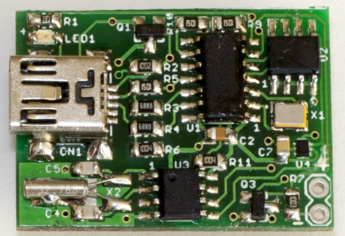
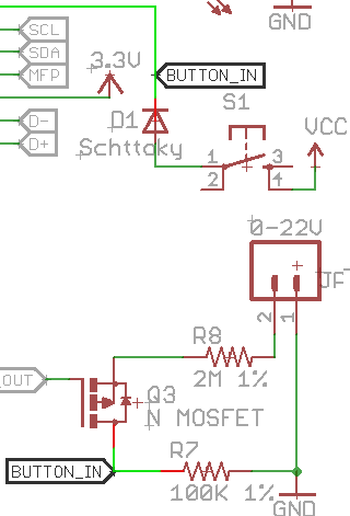
I also received the re-spun PCB, added in a diode as well to protect in case the button is pushed when voltage logging, if a sample is taken there is the possibility that the voltage could reach VCC, but since we have the resistor divider, that voltage would need to be 65V to give 3.1V on VCC, given that the logger will only be rated to 20V, I don’t think it will happen but I’d rather have some form of protection there.
...
// Read delay time
else if (optionSelected == 2) {
	printf("\n--- Read delay time ---\n");
	usb_read_data(USB_DELAY_TIME);
	print_interval_time_from_buffer();
}

// Program function to use
else if (optionSelected == 3) {
	printf("\n--- Program logging function ---\n");
	printf("Please select 1 to log temperature and 2 to log voltage: ");

	int functionSelected = read_number_w_min_max(1, 2);

	// Send to USB device
	clear_buffer();
	buffer[1] = functionSelected;
	usb_send_data(PROGRAM_LOG_FUNCTION, 1);
	verify_data_written(USB_FUNCTION_SELECTED, 1);
}
...
I also cleaned up the code on the PC interface side which should be way easier to read (example above) which brought the line count down 963 from to 663 lines.

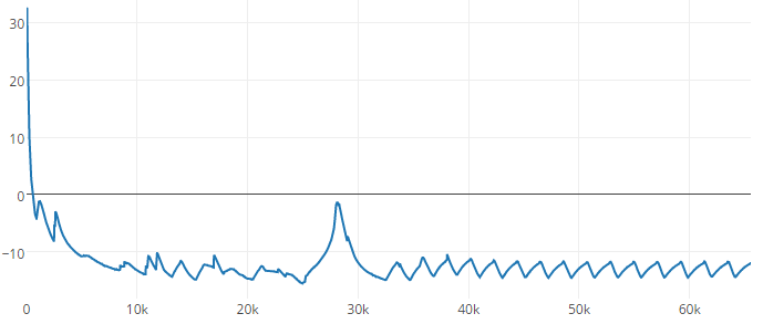
And I think that’s it for this project, it’s now finished, two example logging results above (fridge and freezer). I’ll just need to build a few more of these, do more testing, write up the documentation then they’ll be ready for sale.
Download MiniTempLogger_R5
Building the Mini Temp Logger Part 1: Re-design of the SATVL/A25TTL into another product
Building the Mini Temp Logger Part 2: LDO capacitors checks, testing I2C timings and using EEPROM page writes
Building the Mini Temp Logger Part 3: Using the TMP102 sensor, testing I2C methods and other small improvements
Building the Mini Temp Logger Part 4: Adding RTC and Estimating battery life
Building the Mini Temp Logger Part 5: PCBs arrived and RTC Testing
Building the Mini Temp Logger Part 6: RTC Auto Trim & Voltage reading
Mini Temp Logger v1.0 Released


