From our last part we looked at the new design for a small temperature logger project with a drafted PCB, the redesigned the voltage switching circuit and USB connect/disconnect feature and updating the data transfer function. In this part, we’ll look the capacitors for our LDO (part of the voltage switching circuit), testing our I2C timing to maximise battery life, switching to a 1Mbit EEPROM and using EEPROM page writes.
Usually when I chose capacitors for a voltage regulator, I’ve never really look at the ESR performance of the capacitor before; I assume most capacitors would be good enough for general loads, most of times they are but I thought it would be a good idea to actually test the ESR this time. The 3.3V LDO I went with was the Richtek RT9166 which is low cost and I’ve use other products of theirs (DC-DC) before so it should be a safe choice.
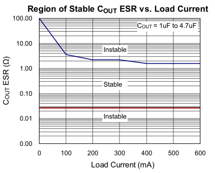
The input capacitance is 1uF minimum without any ESR requirements and output capacitance is also 1uF minimum (X7R) and we’re given a region of stability depending on the load – 0.3 to say 20 ohms for the small amount of current which I’ll need. I purchased one of the many ESR LCR Meter kits available from Ebay and decided to test a few caps, unfortunately it didn’t measure the ESR of some small caps properly (under 1uF) but it works on larger caps.
(image used from meettechniek.info)
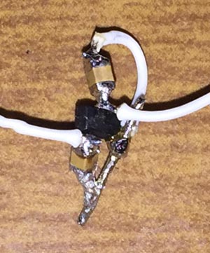
We can use a function generator and oscilloscope to measure the ESR by measuring the voltage change when the current rate changes from the square wave we feed in. My function generator only had a max of 5.2Vpp when I applied a DC offset so we just tweak the calculation slightly: 5.2V / 50 ohms = 104mA current step change.
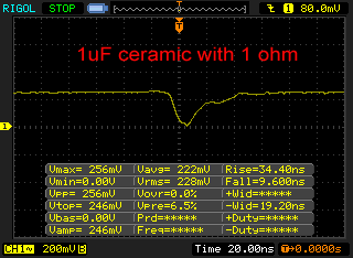
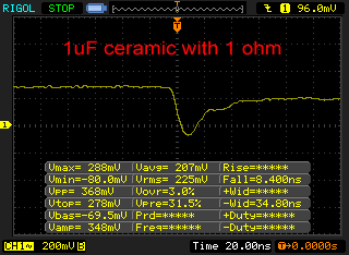
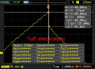
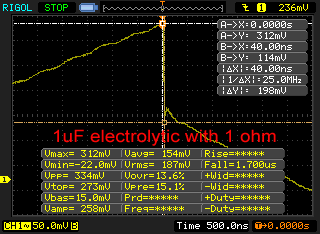
I tested an 1uF electrolytic and the 1uF ceramic capacitor I plan on using at 50 KHz, plus to verify our results I added a 1 ohm resistor in series so we could measure and verify the ESR was correct. As you can see, the current step change looks different between the electrolytic and the ceramic. I’m seeing a 1 ohm ESR on the electrolytic vs 2.5 ohms on the ceramic, when we add the 1 ohm resistor in series, we get 2 ohms electrolytic vs 3.5 ohms ceramic; each ~100mV drop represents ~1 ohm in the ESR.
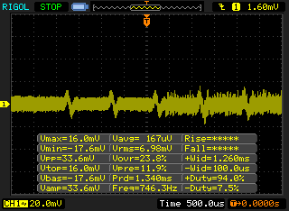
So the ESR is more than I would have expected but as we’re not drawing much current it still is in the region of stability so we are all good there. If we used more than 200mA then our 1uF capacitor wouldn’t cut it. I measured the noise with a 1.5k ohm load and most of the noise I saw was when I connected the ground lead, so it’s likely to be under the 30mVpp but either way it works fine.
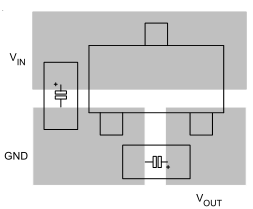
There also appears to be a best practice PCB layout (who would have thought an voltage regulator would need one), the general consensus is to not use any via’s in the PCB design.
Testing I2C timings
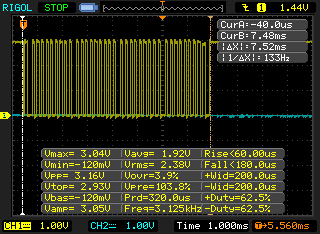
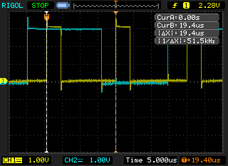
Since we’re dropping from a CR2032 to a CR1022 battery we need to reduce the amount of time that our MCU is awake and thus need to test that our I2C timings are as short as possible. I measured the SATVL and sending the command to write to the EEPROM, it takes us 7.52ms and each clock cycle is 184uS. The general minimum timings for our EEPROM that we need to meet is 2uS for 400KHz I2c.
uint8_t I2C_DELAY_CYCLES = 0;
#define I2C_DELAY_CYCLES_BAT 1 // ~2 us Running at 1.5MHz
#define I2C_DELAY_CYCLES_USB 20 // ~5 us Running at 12MHz
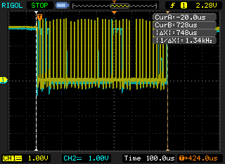
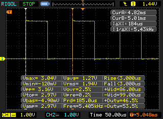
One issue is that the I2C delay won’t be the same when running from the battery (1.5MHz) vs when powered by USB (12MHz), so the simplest solution is to add a variable to choose which delay to use. After verifying the delays on the scope, I went with 1 cycle on battery and 20 cycles when USB powered. The command to write now takes 748uS, we could reduce this a bit more if we optimised the writing loop as there are a few unnecessary ASM commands that are compiled in.
Switching to 1Mbit EEPROM
I looked into upgrading the EEPROM from 512Kbit to 1Mbit and the cost isn’t bad at all, it seems to be a little bit more than 512Kbit price, I’m looking at the CAT24M01.
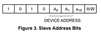
This device sacrifices 1 bit of the device address to add in another bit (a16) for the byte address so there’s some small code changes to make – changing our 16 bit address to 32 bits.
bool soft_i2c_eeprom_write_byte(uint8_t deviceAddr, uint32_t writeAddress, uint8_t writeByte) {

	// Transfer bit 16 in writeAddress to deviceAddr
	if (writeAddress & 0x10000) {
		deviceAddr |= (1<<0);
	}
	uint16_t processedAddress = writeAddress & 0xFFFF;

	// Issue start condition and send device address
	SoftI2cMasterAddress(deviceAddr, processedAddress, NOREPEATSTART);
        ...
We can intercept the writing/reading requests, check if the 16th bit is set in writeAddress and set the last bit on the device address to 1, then re-write the new address as a 16bit so we don’t have to modify the other functions like SoftI2cMasterAddress.
Changing to EEPROM page writes
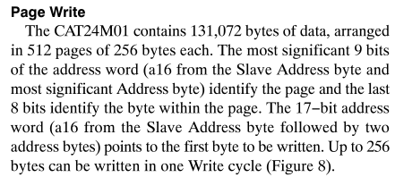
With our 1Mbit EEPROM we have 512 pages consisting of 256 bytes each page and we’ll have to write a new function to cater for this. The first 9 bits set the page and the remaining 8 bits indicate which byte out of 256 we will write to.
bool soft_i2c_eeprom_page_byte(uint8_t deviceAddr, uint16_t pageAddress, uint8_t byteAddress, uint8_t* writeByte, uint8_t writeLength) {
	// If bit 9 is set in page address, set slave Address byte high
	if (pageAddress & 0x100) {
		deviceAddr |= (1<<0);
		pageAddress = pageAddress & 0xFF; // Clear high 8 bits
	}

	// Issue start condition and send device address
	SoftI2cMasterAddress(deviceAddr, (pageAddress << 8) | byteAddress, NOREPEATSTART);

	// Write all the bytes
	for (uint8_t x = 0; x < writeLength; x++) {
		SoftI2cMasterWrite(writeByte[x]);
	}

	// Issue a stop condition
	SoftI2cMasterStop();
	...
}
We have our page address which if the 9th bit is set high, we set the device address last bit high and then we shift the page address to the left by 8 and OR it to our byte address so we send 16 bits for the address. Now we can write up to 256 bytes at once – we have a pointer to the array to write and the length of the array.
#define EEPROM_BUFFER_LENGTH 32
uint8_t eepromBufferCounter = 0;
uint8_t eepromBuffer[EEPROM_BUFFER_LENGTH];
uint16_t eepromPageAddress = 0;
uint8_t eepromByteAddress = 0;
...
eepromBuffer[eepromBufferCounter++] = (calculatedValue >> 8);
eepromBuffer[eepromBufferCounter++] = (calculatedValue & 0xFF);
...
if (eepromBufferCounter >= EEPROM_BUFFER_LENGTH) {
	soft_i2c_eeprom_page_write(EEPROM_ADDR, eepromPageAddress, eepromByteAddress, eepromBuffer, EEPROM_BUFFER_LENGTH);

	eepromByteAddress += eepromBufferCounter;
	eepromBufferCounter = 0;

	if (eepromByteAddress == 0) { // Increment page address
		if (eepromPageAddress == 511) { // EEPROM full
			system_sleep();
		}
		eepromPageAddress++;
		eepromByteAddress = 0;
	}
}
As discussed in my last post, I’m looking to perform a page write every 32 bytes of data we have logged, we’d store the temperature logged in a 32 byte buffer and once that buffer is full, we write all bytes to the page and increment the byte address by 32. Once the written bytes reaches 255, we increment the page address and once the page address reaches 511 and the byte address is also 255, we finish logging by going to sleep until we are woken up.
eepromByteAddress += eepromBufferCounter;
eepromBufferCounter = 0;
...
// Write a blank page before we use the last 32 bytes in the current page
if (eepromByteAddress == 223 && eepromPageAddress != 511) {
	soft_i2c_eeprom_page_blank(EEPROM_ADDR, eepromPageAddress+1);
}
...
Instead of writing a special 2 byte at the end of each logging result like we used to in the SATVL so we knew when to finish transferring the data to the PC, we can simply write the next page as empty in advance once we are coming close to switching pages. Also sort of related, instead of having the delay time programmed into the EEPROM, I’m moving this over to the ATtiny’s EEPROM since the EEPROM will be SMD I expect it won’t be replaced by the user.
Download MiniTempLogger_Proto_R1
That’s all for this part, in the next part we’ll look at adding the TMP102 temperature sensor.
Building the Mini Temp Logger Part 1: Re-design of the SATVL/A25TTL into another product
Building the Mini Temp Logger Part 2: LDO capacitors checks, testing I2C timings and using EEPROM page writes
Building the Mini Temp Logger Part 3: Using the TMP102 sensor, testing I2C methods and other small improvements
Building the Mini Temp Logger Part 4: Adding RTC and Estimating battery life
Building the Mini Temp Logger Part 5: PCBs arrived and RTC Testing
Building the Mini Temp Logger Part 6: RTC Auto Trim & Voltage reading
Mini Temp Logger v1.0 Released


