From our last part we added the RTC including programming the time from the PC, some fixes, estimated battery life and briefly looking at some logging results.
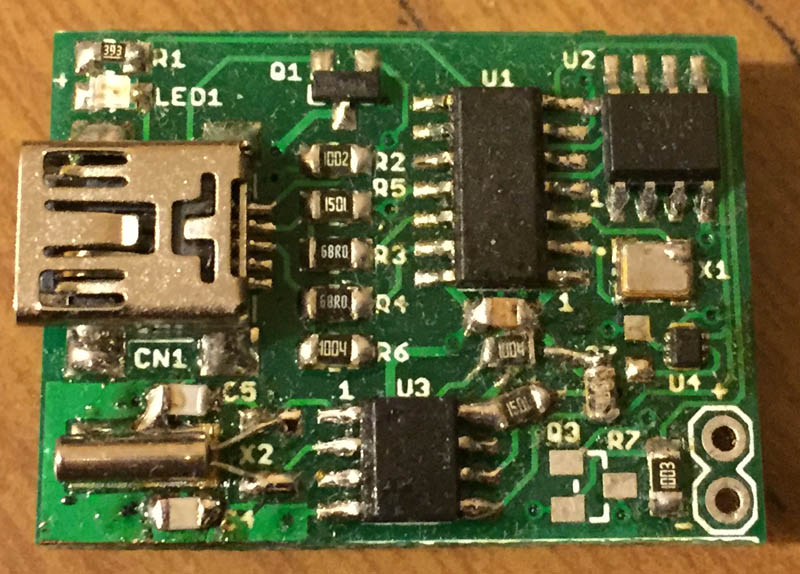
I made a quick couple of changes to the PCB and squeezed the voltage logging back in to just have that option available again, briefly tested the new SOT23-5 LDO without issues. A few weeks later and the PCBs turn up, everything looked good and then I built it and found out I forgot to add the I2C resistors and RTC MFP resistor too! A couple of cuts to the board to reveal the tracks and I could solder the resistors and it works.
I started testing the RTC with different capacitors to see how accurate it can be, it seems to work good for a few hours but eventually it started to drift by a couple of seconds after a day which could be due to temperature changes (15C to 25C) over 24 hours or possibly the PCB design. I have a small single sided RTC PCB for my big clock and that used to be 1-2 seconds drift every month which I’ve had for almost a year though now it’s drifting by 3-4 seconds after a few days too, so it is starting to sound like it could be temperature problem thought it doesn’t seem to be as bad; I have had one day where it didn’t drift and then the next day when it did by a lot.
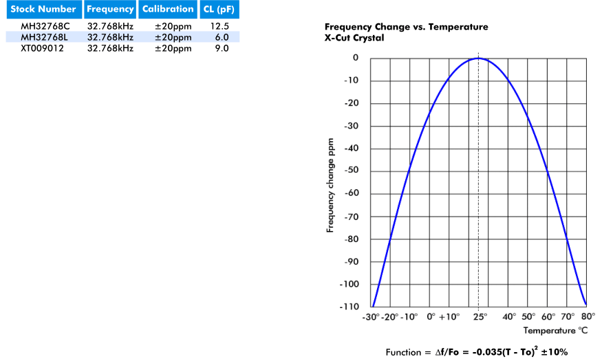
The RTC crystal itself has a calibration ppm on -/+ 20ppm and with the temperature changes, that would result in a 5-10ppm change which should only equate to 2-3 second maximum drift per day assuming the worst scenario. The graph shows a negative ppm if the crystal is exposed to temperatures from 25C. I thought they might have forgotten the + sign from the graph however after testing it for myself with an ice pack placed on the RTC for a few minutes then reading the result and doing the same with a heat gun set to 100C, in both cases the RTC slowed down by 3 to 5 seconds so it is confirmed.
To counteract this, I could potentially set the digital trim to add clock cycles once the temperature changes from 25C each time the temperature is sampled when logging, the only problem is if the logging time is too high (say 3+ hours) and the temperature changes drastically then we may not respond with setting the right digital trim in time. The other place to do this is when we aren’t logging and when the date/time is set, perhaps I will have it wake up every 3 or 6 hours. Compared to the watchdog timer which is about -/+ 10%, we are still in a way better spot with the RTC even without digital trimming. My goal was to have it be 1-2 seconds per month initially however that may not longer be the case, possibly 1-2 seconds per day may be the new goal.
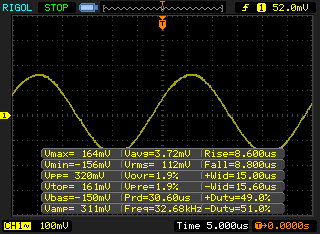
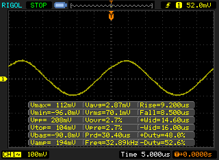
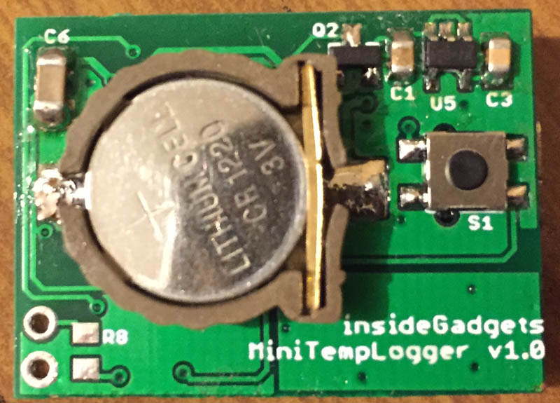
Another odd issue is that blowing on the RTC crystal causes it to stop working for a few seconds (you have to get close, maybe 5-10cm) which I could see with the scope (waveform keeps decreasing in amplitude) but exposing it to a heat gun has no issue; a bit of spray on lacquer seems to solve the problem. I did happen to find some information on RTC’s from Maxim saying that moisture can cause the RTC to stop; it could either be that or somehow I’m generating an electrostatic charge on it?! I didn’t have the RTC case soldered down to ground (some people say you should for mechanical reasons and some say you shouldn’t as you would expose the crystal to high temperatures), I replaced the RTC/capacitors for good measure and grounded the RTC case and that also seems to have solved the blowing on the crystal issue.
13/08/2016 12:48:25 AM	0.06
13/08/2016 12:48:26 AM	0.00
13/08/2016 12:48:27 AM	0.00
13/08/2016 12:48:28 AM	4095.94
13/08/2016 12:48:29 AM	4095.94
13/08/2016 12:48:30 AM	4095.94
13/08/2016 12:48:31 AM	4095.88
There was a bug with negative numbers which I discovered when putting it in the freezer, it would wrap back to 65535 which was my “logging ended” number when reading it out of the PC and I had to make a little change as to how negative numbers were read and changed my logging ended number too.
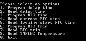
I’ve added a few more features to the PC interface such as reading the current time, reading the temperature, reading the start logging time and read the delay time, some of which helps with testing. Download MiniTempLogger_R4
That’s all I have for an update so far, I’ll be looking to re-spin the board and testing the RTC digital trimming on temperature.
Building the Mini Temp Logger Part 1: Re-design of the SATVL/A25TTL into another product
Building the Mini Temp Logger Part 2: LDO capacitors checks, testing I2C timings and using EEPROM page writes
Building the Mini Temp Logger Part 3: Using the TMP102 sensor, testing I2C methods and other small improvements
Building the Mini Temp Logger Part 4: Adding RTC and Estimating battery life
Building the Mini Temp Logger Part 5: PCBs arrived and RTC Testing
Building the Mini Temp Logger Part 6: RTC Auto Trim & Voltage reading
Mini Temp Logger v1.0 Released


