As part of my CPLD Logic Analyser project, I might want to easily adjust the clock and since the CPLD that I’m using doesn’t have a PLL module, we’ll have to buy our own clock generator.
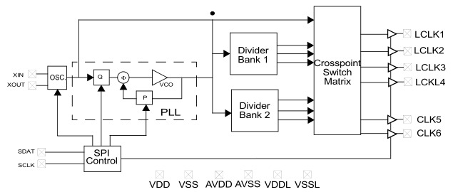
The Cypress CY22150 chip allows you to generate a clock up to 200MHz from a 8-30 MHz crystal using I2C and has multiple outputs / clock dividers. For the price of $2.77 it’s not too bad and for me was actually cheaper than buying a 100MHz crystal from my supplier.
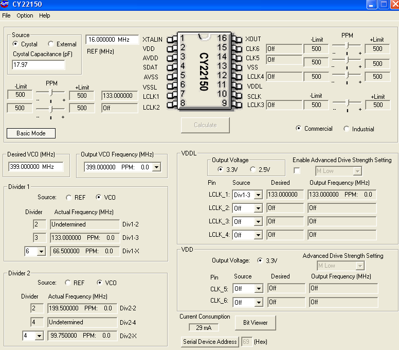
There are a few settings we need to configure – the crystal frequency, crystal capacitors, which outputs to enable and clock multipliers and dividers. This may seem a bit complex at first but Cypress have made a CyberClocks program that can assist us with these settings.
I have a 16MHz crystal, so we enter that on the top left. The VCO is given to us in another section of this program (Option > VCO Calculator) as shown below, I enter in the Reference as the crystal and desired clock as 133MHz.
Just a quick post on oscillators – about every recent microcontroller out there has an oscillator circuit built in, so you just add a crystal with capacitors (sometimes optional) and the MCU does the rest. But what happens for devices that don’t have the oscillator circuit built in, such as a low end CPLD?
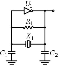
We have two choices – purchase a crystal oscillator or build one yourself. Seeing how I don’t have a crystal oscillator handy, I thought I’d build one.
The configuration I’ll be using is the pierce one, where you have a inverter, a large value resistor such as 1M and the crystal with two capacitors.
A little while ago I saw one of mikeelectricstuff’s videos about interfacing with the iPod nano’s screen using a CPLD. A CPLD is a complex programmable logic device, it’s similar to an FPGA, has a bit less capacity but has its configuration file stored on chip where as the FPGA has its configuration on a memory chip and generally only uses 1 voltage rail.
So what can we use CPLDs for? We can use CPLDs for high speed devices such as an I/O expansion, interfacing with SDRAM, LCDs, combining lots of logic of various chips into one device and so on. An advantage over MCUs is that CPLDs can have multiple logic operations occurring in parallel however it should be noted that with some CPLDs you can only re-program them up to 100 times.
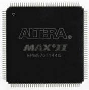
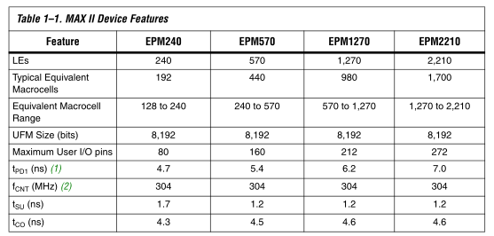
The CPLD we’ll be looking at is the Altera MAXII EPM240 which contains 192 macrocells (the more you have the more logic you can configure), 80 IO pins and can operate at 304 MHz at the highest speed grade. There are also lower macrocell/pin/cost versions of CPLDs too, the Max3000A EPM3064ALC44-10 (100MHz) has 64 macrocells with 34 user pins, is about $3 AUD. It’s in a PLCC package which allows you to use sockets if you don’t want to solder the TQFP package.
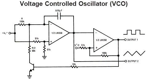
I recently bought a Rigol DS1052E and have been playing around with the different functionality it has. Eventually I came to the point that I’d like to see what frequency does to various components and wanted to build a voltage controller oscillator (VCO).
By using 2 opamps and some passive components we can build a VCO as shown above. But I wanted to make one that was simpler so I looked at the ATtiny25.
ATtiny25 Clockout as VCO
The ATtiny25 has a clock out fuse bit which when enabled, outputs the system clock of the ATtiny but the downside is that you can only run on the internal oscillators when you enable that option. As we do with the SATVL, we can use the 16MHz PLL for our system clock and by modifying the OSCCAL value we can underclock and overclock our ATtiny25 – this is the one VCO method we could use. Download ATtiny25_Clockout
Underclocking and overclocking the ATtiny25 – 10MHz minimum to 33MHz maximum.
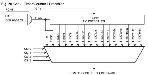
ATtiny25 Timer1 as VCO
But what if we don’t want to overclock our ATtiny25? I didn’t know but you can actually use the PLL as a clock source for Timer1 and we can keep our system clock at 1MHz.
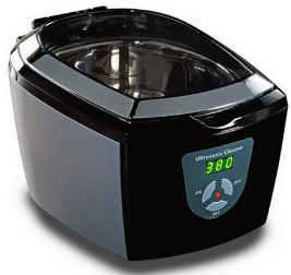
I was given a Visage Ultrasonic Cleaner to see if I could extend it’s timer settings from the maximum setting of 480 seconds to 960 seconds. An Ultrasonic Cleaner uses ultrasound to create small bubbles in the water and when those bubbles collapse it generates enough temperature and pressure to remove dirt and clean objects.
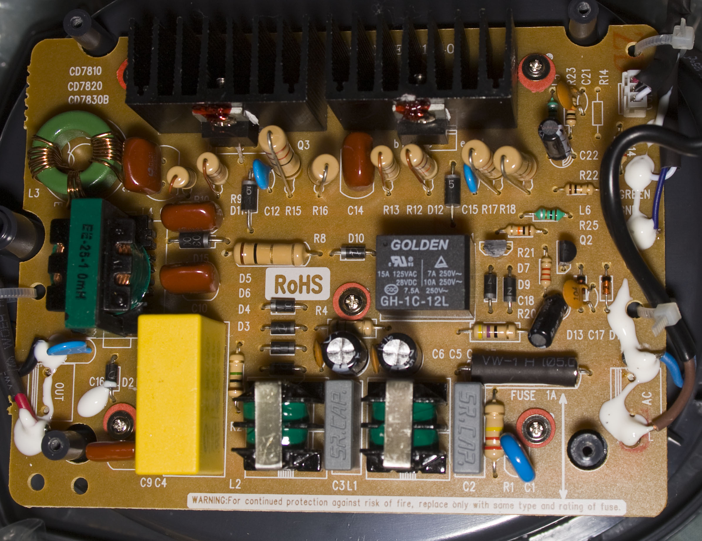
My first thought was that it would have a single board and that I would have to use an ATtiny to press the buttons in a sequence to turn it on for 480 seconds two times in a row. When I went to turn on the Ultrasonic Cleaner to make sure it was operational, it didn’t work. After shaking it a little bit, it seemed to turn on, so something is loose inside.
Upon opening it up, we have the single board but no MCU in sight. The components worth mentioning are the relay and 2 transistors (I assume they are due to the B / E marking) with heatsinks.
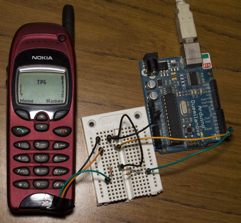
Following on from my post on How to use Nokia F-bus to send an SMS message where I used an Arduino to send an SMS message, at the end I mentioned moving to an ATtiny2313A/4313 so that we don’t need to use the Arduino.
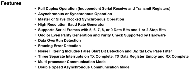
The ATtiny2313A/4313 features Universal Synchronous and Asynchronous serial Receiver and Transmitter (USART) with the features above. The Nokia F-bus uses 115,200 bps with 8 data bits, no parity bit and 1 stop bit.
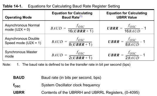
To use USART we need a clock input, there are 3 clock options – Asynchronous Normal, Asynchronous Double and Synchronous Master. For Asynchronous, the clock is generated from the system oscillator where as the Synchronous option is where we provide an external clock signal input. Using the UBRR register we can dial into the baud rate that we want but it depends on the system oscillators frequency.
A few months ago I was looking into how to use Fbus with a Nokia phone but didn’t have much luck and instead just wired up the keypad. I decided to revisit Fbus and this time happened to find some AVR code which could send/receive SMS’s so now I’m able to send an SMS using the Arduino and I’ll explain how we do this.
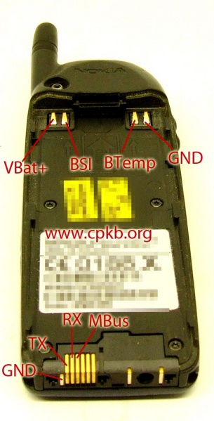
Firstly you need a Nokia phone which the F-bus commands are known, the best documentation is available for the Nokia 6110 and derivatives (Nokia 6130, 6150, 6190, 5110, 5130, 5150, 5190, 3210, 3310) – this was found in \gnokii-0.6.31\Docs\protocol\nk6110.txt
I was able to purchase a Nokia 6150 from Ebay for under $20. You can search up the Nokia pinout for your mobile phone – I found the TX, RX and GND for my phone.
In this video I show how you can use an ATtiny85’s (or any other ATtiny) ADC in differential mode which can be used to calculate the voltage drop on a device that isn’t tried directly to ground, for example, to measure the voltage drop across a shunt resistor to calculate current being drawn.
The differential mode allows for bipolar mode so you can see which input is the positive and negative, you can switch the inputs around in the ATtiny and then use the unipolar differential mode to get the full resolution of 10bits. There are also gain settings which you can enable – 1x or 20x gain.
About a year ago I purchased an ATtiny10 with one of my orders but didn’t get to program it because I didn’t have a programmer and didn’t bother getting one. I was looking at Hackaday – it looks like someone wrote up with an ATtiny10 programmer using the Arduino! You program it by pasting the hex file into the serial window.
If you haven’t seen the ATtiny10 before it’s really small (above is a picture of it next to the ATtiny85) but has minimal features, program space, SRAM, registers and functions. It can run up to 12MHz, has 1KB space, 32bytes SRAM, no EEPROM and an 8-bit ADC.
The majority of users whom use the ATtiny10 seem to use assembly instead of C; some examples of ASM files can be seen on the link above. I wanted to use C on it, however WinAVR which uses avr-libc doesn’t support it so we’ll have to use AVR Studio.
After replacing the battery, it still seemed to have some problems – when it detected movement, it would keep thinking it detected movement and switching the LED on and off every 4 seconds for about a minute or so (or maybe even longer).
Above is the picture of the PCB for reference. I started measuring voltages and compared it to another PIR sensor but there wasn’t a difference in voltage that stood out.
AdvanceVGA – Play your GBA on the big screen! Swap out the LCD for our board, solder some wires, connect 5V USB and VGA and you’re ready to go.
GBxCart RW allows you to backup GB/GBC/GBA ROMs, save or restore game saves and re-write supported flash carts. Mini RW option available for GB/GBC only.
Wireless Gameboy Controller – Use your Gameboy, mGB, GBC, GBA, GBA SP, GB Micro, NDS and NDS Lite as a wireless controller on Windows, Linux, Raspberry Pi, etc, and on your NES, SNES, N64, Gamecube and Wii.