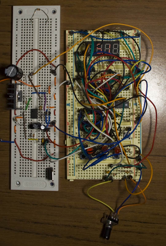
Following on from Part 1, we started to build ourselves a programmable power supply which is working but we’ll be adding more refinements such as adding LEDs for the buttons, using a rotary encoder instead of the voltage up/down button.
(update to SPPS)

The first thing we need to do is use LEDs for each programmable button instead of the 4th segment, we have 4 outputs left from our second shift register, so that’s where we’ll add these LEDs to. Now we can leave the first segment of the LED display blank if it’s under 10V and leave the dot point at the same place. I also moved the set button to be read by the ADC reading the programmable buttons. I’m considering moving to an ATtiny461 to give each button it’s own pin.
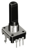
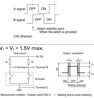
Next we’ll add in the rotary encoder, the way the rotary encoder works is when you rotate the knob it jumps to the next step and when doing so one output goes low before the second output. Rotary encoders can have a different amount of steps, I went with a 24 step one. We can also see the circuit to use above, just 2 resistors from VCC to terminal A and B.
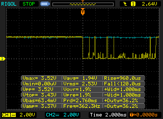
On the scope, it seemed to give the the waveform they show above however sometimes it would have a lot of jitter. I firstly tried to make a fix for this in software however the simpler solution made more sense which was to add some caps.
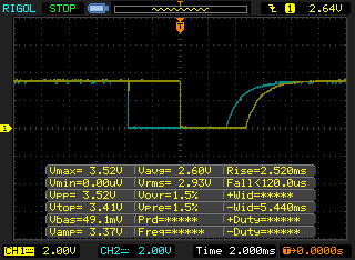
Adding two 0.1uF capacitors seemed to work best, even though they will hinder how quickly rotary the knob, it didn’t make too much of an impact.
// Timer1 compare
ISR(TIM1_COMPA_vect) {
	cbi(TCCR1B, CS10);
	encoderTimeout = true;
}

// Pin interrupt on rotary encoder pins
ISR(PCINT0_vect) {
	// Waiting for either pin to go low
	if (encoderWaitforlow == true && !((PINA & (1<<PA1)) && (PINA & (1<<PA0)))) {
		if ((PINA & (1<<PA1)) && dpotValue < 127) { // See which pin is low
			dpotValue++;
		}
		else if ((PINA & (1<<PA0)) && dpotValue > 0) {
			dpotValue--;
		}

		dpotDisplaycounter = 400;
		double dpotTemp = ((3.3 / ((dpotValue * 0.078) + 10)) * (dpotValue * 0.078)) * 7.76;
		store_number(dpotTemp);

		// Wait for 3ms
		OCR1A = 3000;
		TCNT1 = 0;
		sbi(TCCR1B, CS10);
		encoderWaitforlow = false;
		encoderTimeout = false;
	}
	else if (encoderWaitforlow == false && encoderTimeout == true) { // After the 3ms
		if (!((PINA & (1<<PA1)) && (PINA & (1<<PA0)))) { // If either pin is low, wait another 500uS
			OCR1A = 500;
			TCNT1 = 0;
			sbi(TCCR1B, CS10);
		}
		else {
			encoderWaitforlow = true;
		}
	}
}
As for the code, I’ve added both A and B terminals to trigger a pin interrupt. When the interrupt is triggered we check if either terminal is low and if so, we find out which one is low and change our digital pot value. We then turn on our 16bit timer1 and do a compare for 3000 (3ms). Once timer1 compare is triggered, we switch it off and then when the pin interrupt is re-triggered, we check if both terminals have gone high yet. If they haven’t we do another timer1 compare to 500uS and eventually when both terminals go high again, we start again.
Download SPPS_v0.2
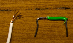
There was one strange thing which occasionally occurred which was the output voltage jumped around quite a bit, about 0.2V -/+ with no load. I decided to redo the circuit on another breadboard but this time use jumper wires instead of cables and that seemed to have sorted it out. Another thing I found was that those cheap jumper cables don’t have many strands of wire in them, so if you were passing 0.5A of current like I was, you start to notice the 0.3V voltage drop. After a bit of testing, I removed the capacitor on the op-amp as that seemed to create more noise than without it.
I was hot swapping capacitors and accidentally swapped in charged capacitor higher than 3.3V to the 3.3V rail and blew up the digital pot. It’s a good thing that happened because upon using another digital pot I found that my, using another one now, but the calibration I previously programmed is off by 0.2-3 volts so eventually we may need a way to auto calibrate the power supply. I’m thinking and playing around with using the second half of the op-amp do this with but we’ll leave this for another part. Also I haven’t added in the 10bit digital pot because I’ve found that a 12bit DAC is the same price so we’ll see how that goes in the next part too.
When swapped out the P mosfet I was using for a IRF9540 which has a RSon of 0.2 ohms, in terms of temperature I didn’t notice any difference. It wasn’t until I loaded the power supply with an 1 amp load running at 5V when I noticed that things were very bad – the heatsink temperature started to rise and reached 85C which is when I stopped the test. What I didn’t realise is that the P Mosfet is dropping 6V which isn’t too bad for low current applications but when you increase the current that’s when things hot. If you ran the 1 amp load at 12 volts, then the mosfet won’t drop much voltage and thus not get hot. After some testing I found that at about 2 watts dissipation I get 74C on the heatsink and for 1.5W I get 58C, so 1.5W for the whole system should be adequate.
At 1.5 watts for the mosfet this means a maximum of (assuming input voltage stays at 13V):
1.8V @ 135mA
3.3V @ 150mA
5V @ 190mA
Which isn’t that great and leads me to a crossroad, should I just stick a beefier heatsink or should I look into switching power supplies / buck converters.
Part 1
Part 2: Added rotary encoder and more testing
Part 3: Back to the LM2596 and calibration
PCBs arrived
Small Programmable Power Supply v1.0 Released


As you’re building a lab power supply I would try to go for the lowest possible noise. So the beefier heatsink it is. You can also try to use multiple transistors in parallel. And if you absolutely can’t live with the wasted energy and generated heat, try a switching pre-regulator.
Thanks, yep that would work.
Also I just found out now that I was using the LM2596 module incorrectly – I didn’t notice the resistor going to ground in the feedback loop, after removing that and wiring it as I should have, now I’m seeing the Vref 1.25V as the maximum voltage that the digital pot will receive.
So I think I’ll just stick that module in and there isn’t any need for the P mosfet, heatsink or opamp, much simpler now but I guess not as satisfying as building it all yourself 😛
The discrete solution should give you lower noise (at least in theory), which is nice to have in lab supply. You could use the LM2596 module as a tracking pre-regulator, then add a filter and a linear regulator.
That sounds like a good idea, thanks, have the LM2596 do most of the voltage reduction and then the linear regulator fine tune it.
[…] LT3080 but has a constant current control loop. Here is an example with an explicit regulator (part 2, part […]