Ever since I did a teardown of the Squeezebox I wanted to re-use the Vacuum fluorescent display which is a MN32032A. It’s running off a 55V power supply, I was able to identify the data lines and by using my 8 channel logic analyser I took a few samples of the data.
Here’s the end result, it works to some degree, as you can see there is some signs of random pixels lighting up which I’ll need to look into at a later stage.
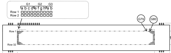
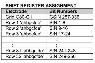
The VFD seems easy enough to use, it’s serial based where you shift out 336 bits containing 32 rows (32 bytes) and 80 grids (10 bytes) but we have to note that when we shift out each row byte it isn’t in the order of abcdefgh but rather ahbhcdfe and that each grid has controls only 4 lights per row. For example, if you were to turn on row 1 and turned on all the grids, a straight line would appear across the screen.
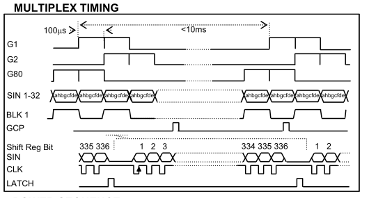
What we’re required to do is shift out 336 bits of which we need to turn on 2 grids at a time, latch the data and cycle GCP. If you do encounter ghosting you can turn the blanking (BLK) high for one time period and then low (however doing this didn’t help the problem I had). I’m not sure as to what the GCP line does but without it the display doesn’t work, it could mean grid control pulse?
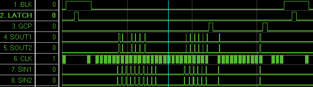
Now we can examine the data we’ve captured. It appear that the BLK doesn’t exactly match the datasheet, the first 8 bits of data occurs when the BLK is high and GCP goes high twice. The time period is about 137uS and by shifting data out to SIN2 as well as SIN1 you can make the pixels display brighter.
uint8_t grid = 0;
uint8_t LEDBuf[40][32];
uint8_t LEDBufHasData[80];

const uint8_t ledLetters[26][32] PROGMEM = {
	{0,0,0,0,31,96,0,63,64,128,128,131,124,
	0,0,0,0,0,128,128,128,128,128,128,128,224}, // a
The way I’ve implemented this is by running an ATmega at 20MHz, having a led buffer of 40×32 and storing some letters with progmem.
if (startup < 200) {
	PORTC |= (1<<BLK);
	startup++;
	_delay_ms(2);
}
...
// Check which grids to light
while (LEDBufHasData[grid] != 1) {
	grid++;
	if (grid == 80) {
		grid = 0;
		break;
	}
}
At startup, we turn on the blanking for a while and then we check which grids have data in them so we know to only light those up otherwise we’ll have flickering if we try to loop through all the grids that have no data.
for (counter = 0; counter < 13; counter++) {
	uint8_t datawrite = 0;

	if (grid % 2 == 0) {
		if (LEDBuf[(grid/2)][counter] & 1<<7) {
			datawrite += 1<<7; // a
		}
		...
	}
	else {
		if (LEDBuf[(grid/2)][counter] & 1<<3) {
			datawrite += 1<<0; // e
		}
		...
	}
	shiftout(datawrite);
}
We write out the rows, in this example, I only care about the first 13 rows. Since each grid is 4 bits we do a mod of the grid by 2 to find out which 4 bits of the row we need to display.
// Grids
int8_t gridcheck = 80;
for (int8_t x = 0; x < 10; x++) {
	gridcheck = gridcheck - 8;

	if (grid == gridcheck) { // a
		shiftout(1);
	}
	else if (grid == gridcheck+1) { // a
		shiftout(3);
	}
	...
	else {
		shiftout(0);
	}
}

PORTC |= (1<<LAT);
_delay_loop_1(2);
PORTC &= ~(1<<LAT);
After shifting out more data and pulsing the GCP line (not shown), we’re ready to shift out the grids by looping 10 times x 8 bits (80 grids) and doing a simple compare check to see which grid to light up then we pulse the latch. Download ATmega_VFD_v0.1
As I mentioned earlier on, I am seeing random pixels being switched on. It seems that if I turn off specific columns from lighting up then the problem mostly goes away. I decided to check my timing compared to the Squeezebox and it seems that what they do in 137uS takes the ATmega about 780uS, potentially this could be part of the problem but I won’t know for sure until I optimise the code and try using hardware SPI to send data out instead of using software SPI, then also try to exactly match the Squeezebox captured data.


