From our last part we made a PCB prototype and looked into how we could expand past two ports using 7400 series logic but in the end it’s easier to use an ATtiny to do this which we’ll take a look at this time plus the PCBs have arrived and I’ve made a case for it.
I went with the ATtiny24 which gives us enough pins to turn on both LEDs, monitor both switches, switch the enables and inputs high or low on our analog switches. After playing around with the expansion line concept which each ATtiny would be connected to, a 1M resistor to ground and 10K resistor to the ATtiny pin to protect it works well.
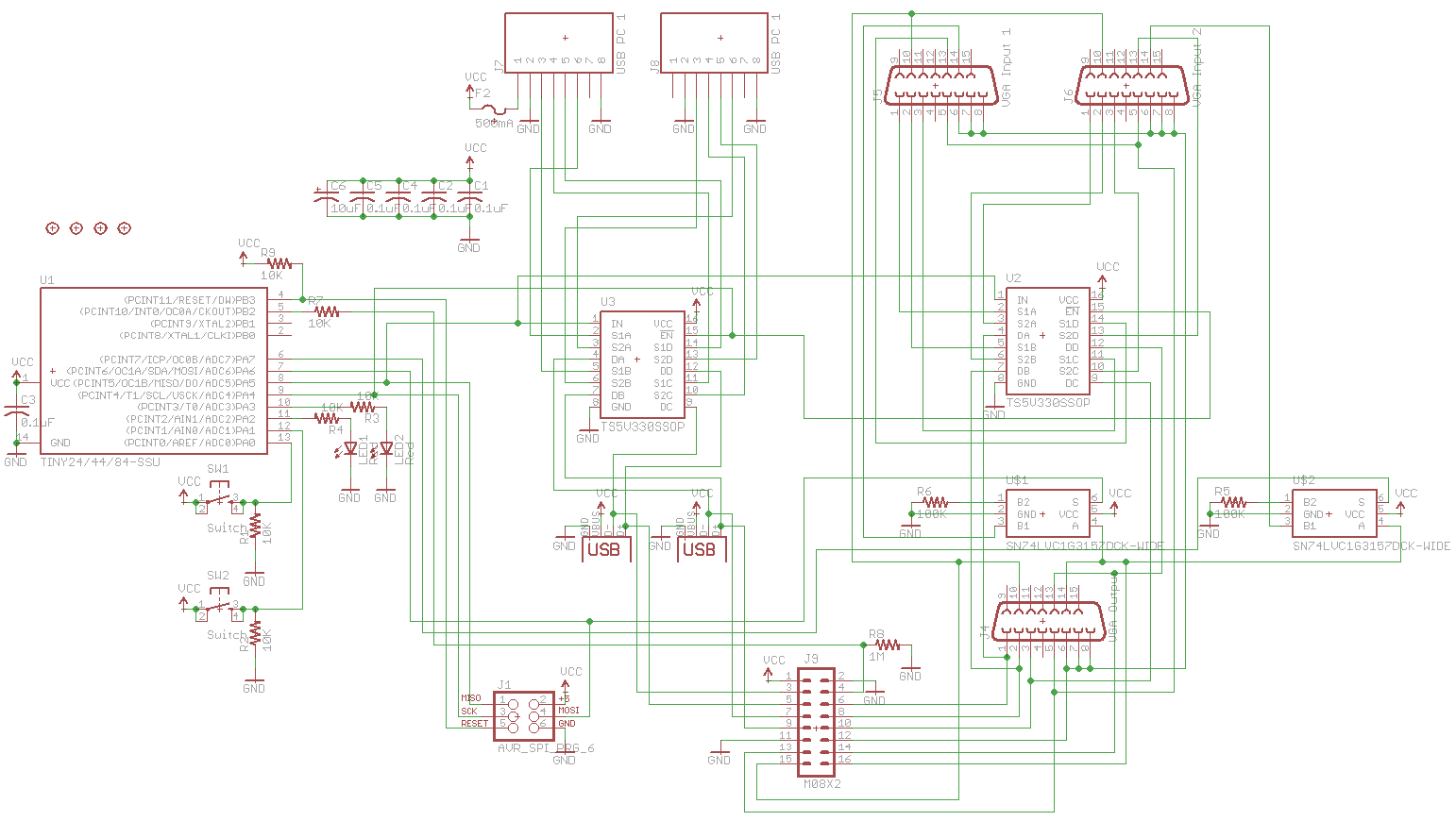
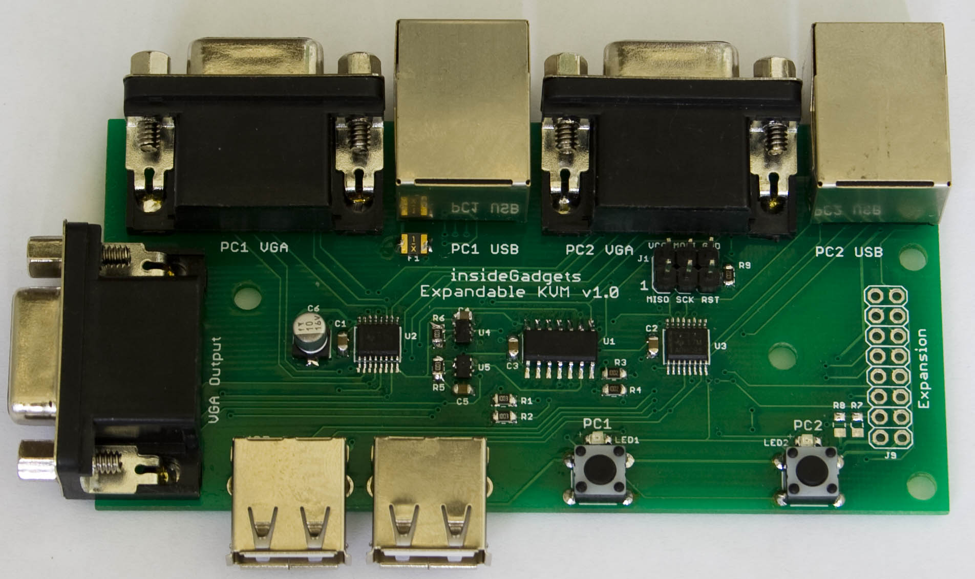
After combining both boards together into one, we have the schematic above. I’ve added the polyfuse, 2x of the SPDT analog switch with a 100K resistor to ground to make 1 side be high impedance, added a programming header, have 0.1uF capacitor on each IC and added a 10uF aluminum SMD capacitor to help with smoothing the power which would eventually go to the expansion boards and to also offer a little bit of voltage spike protection.
Once the PCBs came back, I found that I had the wrong footprint to the SPDT analog switch but managed to solder it, I ordered the correct SPDT part for the future boards. The VGA and Network ports are close together and pretty snug, I might just move them a tiny bit more apart. I was able to test the KVM to 1920×1080 and it performed fine.
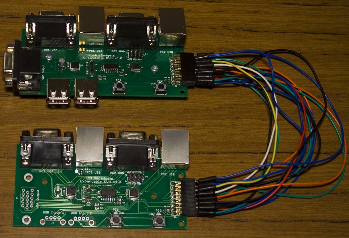
I wanted to test out the expansion functionality to make sure it’ll work, so I built another board and connected the expansion ports up and it’s all working. I was originally thinking of connecting metal pieces with screws so you can secure the expansions together but this would mean it wouldn’t be plug and play and that you’d have to take the PCB out of the case so I decided that the next revision won’t included those mounting holes.
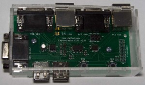
I built a quick case (needs to be re-done) for it and looks like I’ll need longer buttons to poke up at the top of the case and the same could be said for the LEDs however if you weren’t using it with a case then I prefer SMD LEDs to save space. I’m also thinking that a different colour of acrylic could look good here – maybe black.
system_sleep();
_delay_ms(50); // Wait for button debounce

// Check if HighZ pin woke us up
if (PINB & (1<<HIGH_Z)) {
	// High-Z all analog switches
	PORTA |= (1<<QUAD_SW_ENABLE);
	PORTA |= (1<<ANA_SW1_SELECT) | (1<<ANA_SW2_SELECT);
	PORTA &= ~(1<<LED1);
	PORTA &= ~(1<<LED2);
}
else { // Check for button pushes
	if (PINA & (1<<SW1)) { // Change to PC1
		PORTA |= (1<<LED1);
		PORTA &= ~(1<<LED2);

		PORTA &= ~(1<<QUAD_SW_ENABLE);
		PORTA &= ~(1<<QUAD_SW_IN); // Low - PC1
		PORTA |= (1<<ANA_SW2_SELECT); // Disable switch 2
		PORTA &= ~(1<<ANA_SW1_SELECT);

		// Set HighZ pin high for 100ms
		cli(); // Turn interrupts off
		DDRB |= (1<<HIGH_Z);
		PORTB |= (1<<HIGH_Z);
		_delay_ms(100);
		PORTB &= ~(1<<HIGH_Z);
		DDRB &= ~(1<<HIGH_Z);
		sei(); // Turn interrupts back on
	}
	else if (PINA & (1<<SW2)) { // Change to PC2
		...
	}
}
As for the code, it’s pretty straight forward, we monitor the buttons and once they are pressed, we send a signal on the HighZ read/enable pin to tell the other KVMs to go to HighZ mode, then switch in the analog switch to the PC selected and light the LED. We also monitor the HighZ pin to see if other KVMs pulse this pin. Download Expandable_KVM_v1.0
Now I’ll just need wait for the expansion board to arrive and see how we go from there, I wonder how many expansion boards I can add-on until we see some signal degradation.
Building a KVM – Part 1: Selecting switches for video/USB, cabling and using 7400 series logic
Building a KVM – Part 2: PCB Prototype and expanding past 2 KVM ports
Building a KVM – Part 3: Changing to ATtiny24 and PCBs arrived
Building a KVM – Part 4: Expansion board arrived


