From our last part we moved over to the ATtiny24, our PCB arrived, tested good and made a quick case for it. This time we’ll check out the expansion board, a new case with changes needed to make the case work and the KVM board is now available for purchase.
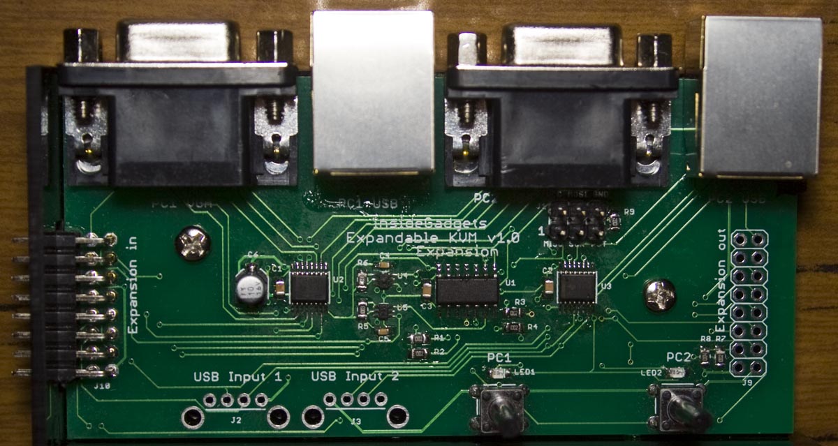
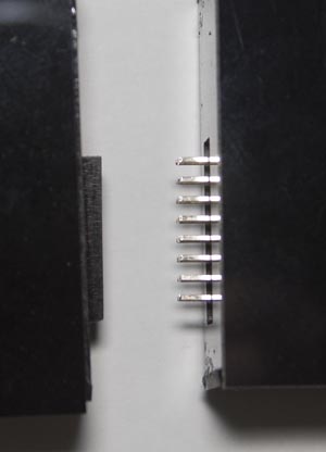
The expansion board has arrived, it’s basically the same as the main board except it’s got a input expansion port instead of the VGA port. One thing I forgot to take out was the USB ports for the expansion board, so potentially if you didn’t want to use the main board’s USB connectors you could use them (I’ll take them out of the next version).
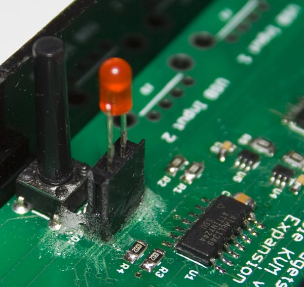
I bought some 20mm buttons and was able to solder in a 2 pin female header on the LED SMD pads so I could attach a 3mm LED to it and added some glue to hold it all in place.
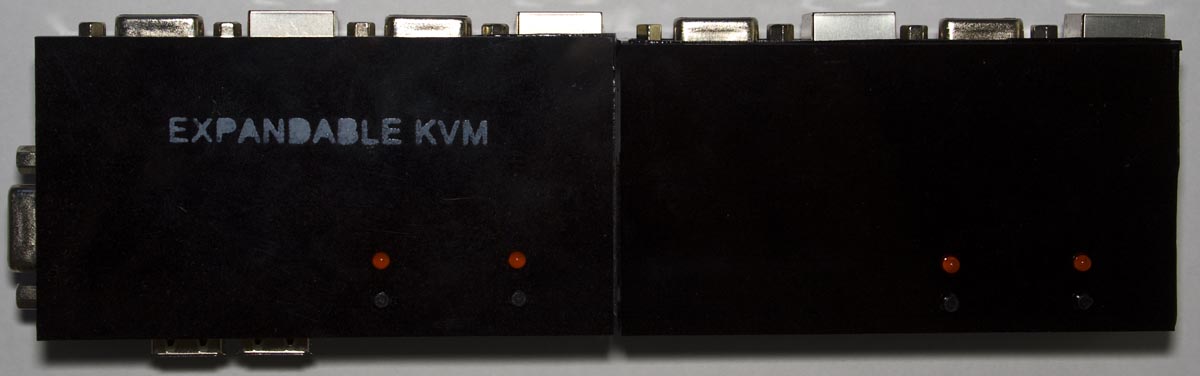
After changing the case colour to black it looks nicer and after connecting the expansion board with case too, it fits pretty well and it works. I need to put some labeling on it, the only viable method I’ve found so far was to make my own stencil from acrylic and then spray paint the name on it, you have to do a light spray otherwise it’ll seek through the stencil.
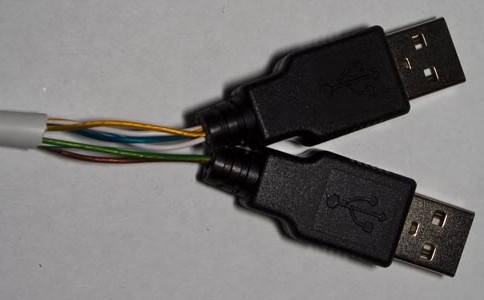
I have been trying out different ways the network to 2 USB cables could be changed to look better – with spray paint, lacquer, heat shrink tubing but unfortunately each way has its own downside so I’ll just be using the plain method which doesn’t look the best but is functional.
I’ve tried some other low current USB devices like memory sticks, hubs – they seem to work fine and bridged the fuse to try out a USB hard drive but it didn’t seem to power up properly, possibly due to the long network cable I’m using but that isn’t a problem for me as it wasn’t ever intended to power up high current devices. When trying to connect to 2 memory sticks, I released I didn’t separate the USB connectors far apart enough, so I’ll do that for the next version.
If you are ready for 0.65mm pin pitch SMD and through-hole soldering, the Expandable KVM kit is now available for purchase – https://www.insidegadgets.com/projects/expandable-kvm/
Building a KVM – Part 1: Selecting switches for video/USB, cabling and using 7400 series logic
Building a KVM – Part 2: PCB Prototype and expanding past 2 KVM ports
Building a KVM – Part 3: Changing to ATtiny24 and PCBs arrived
Building a KVM – Part 4: Expansion board arrived


This is a great project, im very impressed.
I run two server class machines and two desktop ones, could the same principle be applied to these switches for Audio so that if there is no Audio source on the PC in question being used the audio would be held in such a state that no output would occur to the speakers but if you switched to a unit which did have audio enabled it would output to speakers or is analog data of that nature out of the question?